Page 1 :
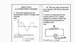
Chapter-07, ALTERNATING CURRENT, Alternating current (AC):, The current or voltage whose magnitude changes continuously with time and its direction reverses periodically is called Alternating current or Voltage (A.C.)., In alternating wave form there are two half cycles, one positive and other negative. These two half cycles make one cycle. Current increase in magnitude in one particular direction attains maximum and starts decreasing, passing through zero it increases in opposite direction and behaves similarly as shown in figure., Expression for alternating current:, I=Im sint, Where, I=instantaneous current, Im = amplitude of current (peak current),, =angular frequency, t=time, Expression for alternating voltage:, V=Vm sint, Where, V=instantaneous voltage, Vm=amplitude of voltage (peak voltage), Direct current (DC):, The current or voltage which does not change direction with time is called Direct current (DC)., Direct current, ,, Where, q=charge flows in a time t., Important terms used in the study of AC, Period [T]: It is the time taken by the A.C to complete one complete cycle of variation. SI unit is second., Frequency []: It is the number of complete cycles of variation of A.C produced in one second., SI unit is hertz (Hz), Instantaneous Value of V and I : It is the value of the alternating voltage or current induced at any instant of time., Peak Value (Vm and Im) ; It is the maximum value of the induced voltage or current. (OR) It is the amplitude of instantaneous voltage or current., Phase: It is the fraction of time period which has elapsed since the current or voltage passed through zero value., Note: We see that, the voltage and the current varies sinusoidally and have corresponding positive and negative values during each cycle. Thus the sum of the instantaneous current values over one complete cycle is zero and the average current is zero. To avoid this difficulty, rms value is taken., R.M.S. Value (Root Mean Square Value) OR Effective value (VRMS and IRMS):, To express A.C. power in the same form as D.C. power , a special value of current is defined and used. It is called, root mean square (r.m.s) OR effective current., The r.m.s current is defined as “The equivalent D.C. current that would produce the same average power loss as the alternating current.”, The r.m.s current is defined by, The r.m.s voltage is defined by, Where, Im= maximum current or peak current, Vm= maximum voltage or peak voltage., Note: The RMS value is also defined as “the square root of the mean of the sum of the squares of all the instantaneous values of voltage or current taken over one full cycle.”, Advantages of A.C., The voltages in A.C. system can be raised OR lowered with the help of a device called transformer. In D.C. system, raising and lowering of voltages is not so easy., In a transmission line, we prefer A.C. transmission because copper loss is lesser and always economical and efficient., Whenever it is necessary, A.C. supply can be easily converted to obtain D.C. supply., Whenever we tune our radio to a favourite station, we are taking the advantage of a special property of A.C. circuits., Note:, A.C. mains frequency is 50 Hertz OR 50 cycles/sec in India., D.C. frequency is ‘0’ Hertz., The A.C. source is called oscillator. The symbol of AC source in a circuit is, Representation of A.C. Current and voltage by Rotating vectors – Phasors:, In order to show the phase relationship between voltage and current in an A.C. circuit, we use the notion of phasors. A phasor is a rotating vector which rotates about the origin with angular speed ‘’ as shown in figure. Rotating vector rotates in anticlockwise direction., A.C. voltage applied to resistor:, The resistor is connected to A.C source as shown in figure. A.C. voltage of a source is given by, V = Vm sint (1), Where, Vm = amplitude of voltage or peak voltage and, = angular frequency., Let, I=alternating current, R=resistance of resistor,, VR=IR=Potential difference across R., According to Kirchhoff’s loop rule,, V=VR, (2), Where, Im==amplitude of current (peak current), Comparing equation (1) and (2), it is observed that the voltage (V) and current (I) are similarly varying and are in phase. The phase relationship between V and I is shown vectorically (Phasor diagram) as shown in the figure., Phasor diagram Graph of V and I verses t, Note: In an A.C. circuit containing R, both V and I reach zero, maximum and minimum values at the same time, clearly voltage and current are in phase each other., Phase difference between V & I = = zero, Derive an expression for instantaneous power dissipated in the resistor:, We know that,, The average value of ‘P’ over a cycle is, Since are constant,, ------------ (1), We have, = and since,, Equation (1) becomes,, Thus,, A.C. Voltage applied to an inductor, The inductor of negligible resistance is connected to A.C. source as shown in figure., A.C voltage of the source is given by, . -----------(1), Let, L= self inductance of an inductor (coil), I= Alternating current., emf induced across L is, ., According to Kirchhoff’s loop rule,, Then,, Integrating on both sides with respect to time,, And get,, + constant, ----------(2), Where, = peak current, Comparing equations (1) and (2) it is observed that the current lags (behind) the applied voltage by as shown., Phasor diagram Graphical representation, Inductive reactance (XL) : It is the opposition for the flow of A.C in an inductance coil., SI unit of Inductive reactance is Ohm ()., We have,, But,, or (But, =2), Note: The quantity ‘L’ is analogous to the resistance and is called inductive reactance denoted by ‘’. Inductive reactant is directly proportional to frequency., Prove that instantaneous power in an inductive circuit is zero:, The instantaneous power supplied to the inductor is, P, So, the average power over a complete cycle is, =, But the average of sin(2t) over a complete cycle =0, ,, Thus, the average power supplied to an inductor over complete cycle is zero., A.C. Voltage applied to a capacitor:, The capacitor is connected to A.C source as shown in figure. A.C voltage of a source is given by V = Vm sin t ------------(1), Let, C=capacitance of a capacitor, q=the charge on the capacitor at any time ‘t’., The instantaneous voltage ‘VC’ across the capacitor is, (2), According to Kirchhoff’s loop rule,, V = VC, q = CVm, Instantaneous flow of current = Rate of flow of charges, Then,, I =, (3), Where, , Im = amplitude of the alternating current., From Equations (1) and (3), it is observed that the current leads (ahead) the voltage by as shown, Phasor diagram Graphical representation, Capacity reactance (XC) : It is opposition for the flow of A.C. in capacitor. SI unit is ohm ()., We have, Im=CVm, Where,, Capacitive Reactance is inversely proportional to frequency and the capacitance., Prove that Instantaneous power in a Capacitive Circuit is zero:, The instantaneous power supplied to the capacitor is, P =, Average power is, but, over a complete cycle, A.C. Voltage applied to a series LCR circuit (Derive an expression for impedance and maximum current of LCR circuit using phasor diagram:, Inductor, capacitor and resistor are connect in series with A.C source as shown in figure., A.C Voltage of the source is given by, ---------------(1), Where, Vm=amplitude of alternating voltage., Let, q= the charge on the capacitor, L=self inductance of a coil,, C=capacitance of capacitor, R=Resistance of resistor,, I= current in the circuit, t=time, The A.C. current in the circuit is same in each element at any time. Let it be, ------------ (2), Where, ‘’ is the phase difference between the voltage across the source and the current in the circuit., `From the Phasor diagram we came to know that and ‘’ represent the voltage phasor across inductor, resistor, capacitor and the source., is parallel to I, is behind I and is ahead of ‘I’., From phasor diagram(a), are always along the same line and in opposite directions., Net magnitude of voltage is ., From phasor diagram(b), According to Pythagoras theorem,, ---------- (3), Where, =magnitude of voltage across R,, =magnitude of voltage across C, XC=capacitive reactance,, =magnitude of voltage across L, XL=inductive reactance,, Equation (3) becomes,, ------------ (4), This is the expression for amplitude of current., In an A.C. circuit, ---------------(5), Where, Z=impedance, From equations (4) and (5), This is the expression for impedance of LCR circuit., Note:, The opposition for the flow of A.C in LCR circuit is called impedance (Z). SI unit is ohm ()., From the impedance diagram, If XL>XC then, But, XL=L and XC=, Phase Relationship w.r.t. LCR circuit:, Case (i): When is positive and the circuit is predominantly Capacitive Circuit, Consequently, the current in the circuit leads the source voltage as shown., Case (ii): is negative and the circuit is predominantly Inductive Circuit. Consequently current in the circuit lags the source voltage., Then, Derive an expression for maximum current in LCR circuit by analytical solution:, According to Kirchhoff’s loop rule voltage equation for LCR circuit is, -------- (1), Where, L=self inductance of coil, R=Resistance or resistor, C=capacitance of capacitor, q=charge, I=current in LCR circuit, But, ,, equation (1) becomes, ---------(2), The above equation is like equation for forced damped oscillation., Let us assume a solution, , Where, qm=maximum charge, ------------ (4), ----------- (5), Substituting equations (3), (4) and (5) in (2), Multiplying and dividing above equation by Z, -------------- (6), Let,, Equation (6) becomes,, After solving, it is found that, Where,, Resonance:, An interesting characteristic of the series LCR circuit. The phenomenon of resonance is common among systems that have a tendency to oscillate at a particular frequency. This frequency is called the system’s natural frequency., Define resonance: The phenomenon at which inductive reactance is equal to capacitive reactance and impedance of LCR circuit is minimum is called resonance., Define resonant frequency:, It is particular frequency at which inductive reactant is equal to capacitive reactance and impedance of LCR circuit is minimum., Conditions for Resonance:, From the LCR series circuit, we found that the current amplitude is given by, Where, and . So, if ‘’ is varied, then at a particular frequency ,, and the impedance is minimum., Then,, This condition is called Resonant condition. The frequency occur is called the resonant frequency ‘’., Derive an expression for resonant frequency:, At resonance, , Where, XC= capacitive reactance,, XL= inductive reactance., But,, This is the expression for resonant frequency., Note: At resonance,, Current is maximum i.e.,, Impedance is minimum i.e., Z = R., ., It is important to note that resonance phenomenon is exhibited by a circuit only if both ‘L’ and ‘C’ are present in the circuit. Only then do the voltages across ‘L’ and ‘C’ cancel each other (both being out of Phase) and the current amplitude is , the total source voltage appearing across ‘R’. This means that we cannot have resonance in a RL (or) RC circuit., Band width of LCR circuit:, The difference between two frequencies for which the current is times its maximum current is called band width., Band width=12, Let, 0=resonant frequency, 1 and 2 = two frequencies for which current is, But, 1>0 and 2<, 1=0+ and 2=0-, But, bandwidth =1-2, = 0+-(0-), Bandwidth=2, SI unit is radian/sec (or) hertz., Note: At 1 and 2, the power dissipated by the LCR circuit becomes half., Define sharpness or quality factor:, It is defined as the ratio of resonant frequency to the bandwidth, Note: Smaller the value of , the sharpner (or) narrower is the resonance., Derive an expression for sharpness of Resonance on the basis of quality factor ‘Q’:, The amplitude of the current in the series LCR circuit is given by, ------------ (1), At a particular frequency, say =1 and =2, then, becomes ., From the resonant curve shown, we see that there are two such values of ‘’ say and , one greater and the other smaller than and symmetrical about . We may write, Squaring on both side,, -------------- (2), But, 1=0+, equation (2) becomes, ----------- (3), At resonance XL=XC, Equation (3) becomes,, ---------- (4), We can approximate, as Since, ., Equation (4) becomes,, Or, But, sharpness, Sharpness=, The ratio is also called quality factor, (Q) of the circuit, Note1: Band width (2)=, So, larger the value of ‘Q’, the smaller is the value of 2 or the bandwidth and sharper is the resonance., Note2: We can also prove that :, Sharpness = Q-factor = ., Applications: Resonant circuits have a variety of applications., i) In tuning of Radio and TV receivers., ii) These circuits helps in accepts signals from many broadcasting stations., Derive an expression for Average Power in A.C. circuit (Power factor):, Consider series LCR circuit connected to A.C source., A.C voltage is, V=Vmsint, and current in the LCR circuit is, I=Insin(t+), Where,, There fore, the instantaneous power ‘P’ supplied by the source is, P (1), The average power over a cycle is given by the average of the two terms in R.H.S. of equation (1). It is only the second term which is time dependant. Its average is zero (the positive half of the cosine cancels the negative half). i.e. ., This can also be written as, Define the term power factor (cos ):, Power factor is defined as cosine of phase difference between current and voltage., OR, It is also defined as the Ratio of circuit resistance to impedance, i.e., cos =, Note:, w.r.t A.C. cos varies from 0 to 1,, w.r.t D.C. cos = 1., The power factor in a LCR circuit is measure of how close the circuit is to expending the maximum power., What are the variations in cos (power factor) w.r.t following circuits?, Case (i): Resistive circuit: If the circuit contains only pure ‘R’, it is called resistive circuit. In that case =0, cos = 1. There is maximum power dissipation., Case (ii): Purely Inductive (or) Capacitive Circuit: If the circuit contains only an inductor (OR) capacitor, we know that the Phase difference between voltage and current is OR 900, i.e., = 900. Therefore cos=0, and no power is dissipated even though a current flowing in the circuit. This current is sometimes referred to as wattles current., Case (iii): LCR Series circuit: , So, ‘’ may be non-zero in RL, RC and RLC circuit. Even in such cases, power is dissipated only in the resistor., Case (iv): Power Dissipated at resonance in LCR circuit: At resonance and = 0. Therefore, cos=1 and , That is maximum power is dissipated in a circuit (through R) at resonance, Derive an expression for frequency of LC – Oscillations and energy stored in it:, A circuit containing an inductor ‘L’ and a capacitor ‘C’ (initially charged) with no A.C. source and no resistor exhibits free oscillations., Let a capacitor be charged ‘qm’ (at t = 0) and connected an inductor as shown in figure., The moment the circuit is completed, the charge on the capacitor starts decreasing, giving rise to current in the circuit. Let ‘q’ and ‘i’ be the charge and current in the circuit at time ‘t’. Since is positive, the induced e.m.f in ‘L’ will have a polarity as shown, i.e.,, Then, Dividing by ‘L’,, ----------- (1), But, (in the present case as ‘q’ decreases, ‘I’ increases), Therefore equation (1) becomes, Or, This equation has the form for a simple harmonic oscillator., The charge, therefore, oscillates with natural frequency, ‘q’ varies as q=qm cos(0t+) and ‘I’ varies as I=Im sin(0t+), Where, Im=qm., Energy stored in charged capacitor is, . At this time no current flows through L., Total energy of LC circuit is ., Explain with circuit diagram how the LC elements sustains the oscillation, The above figure (a) shows a capacitor with initial charge ‘’ connected to an ideal inductor. The electrical energy stored in the charged capacitor is . Since, there is no current in the circuit, energy in the inductor is zero. Thus the total energy of LC circuit, At t = 0, the switch is closed and the capacitor starts to discharge as shown in fig (b). As the current increases, it sets up a magnetic field in the inductor and thereby, some energy stored in the inductor in the form of magnetic energy i.e., . As the current reaches its maximum value as shown in figure (c), all the energy is stored in the magnetic field The capacitor now has no charge and hence no energy. The current now starts charging the capacitor as shown in figure (d). This process continues till the capacitor is fully charged . From the figure (e) the capacitor is charged with opposite polarity to it’s initial state w.r.t figure (a). The whole process will now repeat itself till the system reverts to its original state. Thus, the energy in the system oscillates between the capacitor and the inductor., Note:, An oscillator merely as an energy converter. It receives D.C. energy (power) and changes it into A.C. energy power of desired frequency., An oscillator employs positive feed back., In an LC-Oscillator, the frequency of oscillation is inversely proportional to square root of L and C., LC oscillation will be damped by two reasons:, Every Inductor has some resistance the effect of this resistance is to introduce a damping effect on the charge and current in the circuit and oscillation and finally die away., Even if resistance is zero, the total energy of the system would not remain constant. It is radiated away from the system in the form of electromagnetic waves., Note-5: Analogies between mechanical and electrical quantities:, Transformer:, It is a device used to vary the alternating voltage from few volts to several million volts., Principle of Transformer:, The transformer works on the principle of mutual induction., Note: It is necessary to change OR transform an alternating voltage from one to another of greater OR smaller value. This is done with a device called transformer using the principle mutual induction without change in frequency but there is a change in voltage level., Construction:, A transformer consists of two sets of coils, insulated from each other. They are wound on a soft iron core, either one on top of the other a shown in fig (a) OR on separate limbs of the core as shown in figure (b). One of the coil called the primary coil. The other coil is called the secondary coil. Often the primary coil is the input coil and the secondary coil is the output coil of the transformer., Working Principle: When an alternating voltage is applied to the primary, the resulting current produces an alternating magnetic flux which links the secondary and induces an e.m.f in it. The value of this e.m.f depends on the number of turns in the secondary. We consider an ideal transformer in which the primary has negligible resistance and all the flux in the core links both primary and secondary windings. Let ‘’ be the flux in each turn in the core at time ‘t’ due to current in the primary, when a voltage ‘’ applied to it. Then the induced e.m.f OR voltage ‘’, in the secondary with ‘’ turns is, The alternating flux ‘’ also induces an e.m.f called back e.m.f in the primary. This is, But,, (1), (2), From equations (1) and equation (2), (3), If the transformer is assumed to be 100% efficient (no energy losses) w.k.t, Input power = Out Put Power and P = VI, (4), Then combining equation (3) and (4) we have, (5), Since ‘I’ and ‘V’ both oscillate with same frequency as the A.C source., Now, we can see how a transformer affects the voltage and current we have, Step-Up transformer: If the secondary coil has a greater number of turns than the primary , the voltage is stepped up . This type of arrangement is called a step-up transformer., However in this arrangement there is less current in the secondary than in the primary (i.e., )., Step-Down transformer: If the secondary coil has less turns than the primary . In this case, and . That is the voltage is stepped down, OR reduced and the current is increased., Step – Up transformer Step – Down Transformer, Explain briefly the power losses in a transformer?, In actual transformers, smaller energy losses do occur due to the following reasons;, i) Flux leak loss, ii) Resistance of the windings loss (Copper loss), iii) Eddy current loss and, iv) Hysteresis loss, Flux leakage: There is always some flux leakage. That is not all the flux due to primary passes through the secondary due to poor design of the core OR the air gaps in the core. It can be reduced by winding the primary and secondary coils one over the other., Resistance of the windings: The wire is used for the windings has some resistance and so, energy is lost due to heat produced in the core winding (i.e., I2R loss). In high current, low voltage windings, these are minimised by using thick wire., Eddy current loss: The alternating magnetic flux induced eddy currents in the core and causes heating. The effect is reduced by having a laminated core., Hysteresis loss: The magnetisation of the core is repeatedly reversed by the alternatively magnetic field. The resulting expenditure of energy in the core appears as heat and is kept to a minimum by using a magnetic material (i.e. mild steel is used) which has a low hysteresis loss., Note: Rating of transformers is expression in KVA (Kilo–Volt Amperes), Applications of transformers:, It is used in power supplies., Used in modern computers, Used in motor control devices, Used in stabiliser, Using in rectifier and filter circuits, Used in wave analysers etc., One Marks Questions:, Define alternating current., Define peak value of voltage and current., Define r.m.s value., How is r.m.s voltage of ac related to peak value of ac voltage? (March-2014), What is resonance?, Define resonant frequency., What is quality factor (sharpness)?, Define power factor., Define stepup transformer., Two marks questions:, Write the condition for resonance., Derive the expression for resonant frequency., Distinguish between inductive reactance and capacitive reactant., Three Marks Questions:, Explain the construction of transformer. Mention its principle. (March-2014), Derive an expression for resonant frequency of series circuit containing inductor, capacitor and resistor (July-2014), Show that voltage leads currents when AC voltage applied to pure inductance. (March-2015), Show that voltage leads currents when AC voltage applied to pure capacitance., Show that voltage leads currents when AC voltage applied to pure resistance., What is the principle behind the working of a transformer? Mention any two sources of energy loss in transformer. (July-2015), What is a transformer? Mention two sources of energy loss in a transformer. (March-2016), With a diagram, Explain the working of a transformer. (July-2016), Five Marks Questions:, Derive an expression for impedance and current of LCR series circuit., Derive an expression for frequency of LC-Oscillations and energy stored in it., Derive an expression for sharpness of Resonance on the basis of quality factor ‘Q’., ********