Page 1 :
UNIT-I, INTRODUCTION OF ENERGY SOURCES AND ITS CONVERSION, Energy, •, •, •, , Energy is the quantitative property that must be transferred to an object in order to, perform work on, or to heat, the object, The SI unit of energy is the joule, which is the energy transferred to an object by the, work of moving it a distance of 1 metre against a force of 1 newton., 1 J = 1 N.m 1 kcal = 4.18 kJ., , Power, •, •, •, •, , Power is the rate of doing work or of transferring heat, i.e. the amount of energy, transferred or converted per unit time., SI units are watt (W)., Power = Work/ time, 1 W = 1 J/s, , Contribution of different types of-power plants is approximately, I., II., III., IV., V., VI., , Steam Power Plants, Hydro Electric Power Plants, Nuclear Power Plants, Gas Turbine Plants, Diesel and Wind Plants, Others, , 58 %, 26 %, 02 %, 10 %, 03 %, 01 %, , CLASSIFICATION OF ENERGY SOURCES, Energy sources are used as fuels. Fuel is burned in machinery to produce work or heat., When fuels are used for producing electricity, heat or motion causes a generator to rotate,, creating electricity for everyday use in homes and businesses., Two categories of energy sources are renewable and non-renewable., 1. Renewable Energy:, •, •, •, •, , Solar Energy, Wind Energy, Biomass and Biofuels, Water and geothermal, , 2. Non Renewable Energy: Fossil fuels and nuclear materials are removed from the earth, and can be depleted
Page 2 :
•, •, •, •, , Coal, Nuclear, Oil, Natural gas, , The two major sources of energy can be classified under:, I., II., , Conventional Sources, Non-Conventional, Conventional Sources, , What are Conventional Sources of Energy?, These sources of energy are also known as non-renewable, renewable sources of energy and are, available in limited quantity apart from hydro, hydro-electric power., What are Non-Conventional, Conventional Sources of Energy?, These non-conventional, conventional sources are also known as renewable sources of energy., energy Examples, include solar energy, bio-energy,, energy, tidal energy and, an wind energy, , THERMAL ENERGY, •, •, , •, , Thermal energy comes under the conventional energy sources which is produced by, burning of fuel (combustion)., In the boiler, steam is produced due to combustion of fuel, that is chemical energy of, fuel is utilized to generate high pressure and high temperature steam in boiler, (chemical energy is converted into heat energy)., This steam is used in a turbine to produce, produce mechanical energy (power). Finally, mechanical energy is converted into electrical energy in generator., , MECHANICAL ENERGY, •, , Mechanical energy is available in two forms, Kinetic and potential energy.
Page 3 :
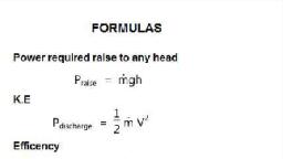
•, , The kinetic energy of a moving body is measured by the amount of work which has, been done in bringing the body from rest position to its present position and viceversa., , •, , Kinetic energy is given by, , •, , Where, m = mass of body (kg) v= velocity of body (m/s) Unit of Kinetic energy is in, joule or kilo-joule, The potential energy is given by P.E. = mgh, Where, m = mass of body (kg), g = acceleration due to gravity = 9.81m/s2, h = head, of body above earth surface (m), , •, •, , ., , =, , HYDROPOWER ENERGY, •, •, •, •, •, •, , Hydropower energy comes under the conventional energy sources., Water from reservoir flows through penstock to turbine. The potential energy of, water is converted into kinetic energy., The high velocity jet created by nozzle attached to penstock., Jet strikes turbine vanes where kinetic energy is converted into mechanical energy, and finally mechanical energy converted into electric energy in a generator., Hydropower Energy is given by P = ρQgHη, Where ρ = density of water (kg/m3) ,Q = discharge (m3/s), g = gravitational, acceleration (m/s2), H = water head (m) η = efficiency of turbine., , NUCLEAR ENERGY, •, , •, , •, , Nuclear energy produced by nuclear reaction by fission is used for generating, steam. This steam is further utilized in a conventional power plant for running, steam turbine and generator., Nuclear energy used for power generation is unstable atoms such as thorium, (Th232), uranium (U236) or artificially produced element plutonium (Pu239). In, atomic fission reaction, the heavy nucleus like uranium is split into two or more, lighter nuclei having a combined mass less than the parent nucleus., The reduced mass is converted into enormous energy in accordance with Einstein, mass energy equation given by E = mc2 Where, E = Energy released. C = the speed of, light. (c = 299793 km/s), , SOLAR ENERGY, •, •, , Solar energy exists within the core of the sun. The temperature and pressure are so, intense that nuclear reaction takes place., This reaction causes four protons or hydrogen nuclei to fuse together to form one, alpha particle or helium nucleus. The alpha particle is about 0.7% less massive than, the four protons.
Page 4 :
•, , The difference in mass is expelled in the form of energy and carried to the surface of, the sun, through a process known as convection, where it is released as light and, heat., , GEOTHERMAL ENERGY, •, , •, , •, , •, , The word "Geothermal" comes from the Greek words geo (earth) and thermal, (heat). It means the heat is stored in the earth's crust. This is thermal energy, trapped beneath and within the solid crust of the earth. This energy exists in the, form of steam, hot water, and/or hot and molten rock. It is released naturally in the, form of geysers, hot springs and volcanic eruptions., Geothermal energy comes from two sources. It includes primordial thermal energy, which was present when the earth was formed as well as the thermal energy, produced from the decay of heavy radioisotopes within the earth., Geothermal energy sources generally come in following categories, I., Hydrothermal energy sources are those associated with steam and heat, II., Petro thermal energy sources are associated with rocks., III., Geo presumed systems occur at high temperature and high pressure., The hydrothermal geothermal sources are further classified as dry steam fields, wet, steam fields and hot water. Hot dry rocks, volcanoes, magma deposits and geopressure fields come under petro thermal energy sources., , WIND ENERGY, •, , •, , •, , •, , The wind mill consists of a propeller driven generator installed on a tower. The, propeller is connected to the generator through gears. The propeller is kept in the, direction of the wind and it drives a generator which produces electric energy., Such a system is used for small power generation capacity. The fluctuation of wind, velocity is the main drawback of this process generating system. There is a large, scope of harnessing wind power to meet the growing demands for energy especially, in the rural area of our country., A wind turbine converts the kinetic energy of the wind into mechanical energy., Wind spins the blades on the wind turbine. When the wind flows around the blade, a, low pressure zone gets developed on the backside of the blade., The shaft goes through a gear transmission box where the turning speed is, increased. The transmission is attached to a high speed shaft which turns a, generator that makes electricity. The electricity thus obtained can then depend on, the end user's need, either alternating or direct. Direct current can be generated by, driving brushless D.C. generator attached to the windmill's rotor., , HYDROGEN ENERGY, •, , Hydrogen is an environmentally eco-friendly alternative to fossil fuels. It can be, used to power just about any machine needing energy.
Page 5 :
•, , •, •, •, , The hydrogen fuel cell, which is the energy conversion device that can capture and, use the power of hydrogen effectively, is the key to making this happen. Hydrogen, fuel is a zero emission fuel when burned with oxygen. It can be used fuel cell, vehicles or electric devices. The energy released enables hydrogen to act as a fuel in, an electrochemical cell, that energy can be used with relatively high efficiency., Stationary fuel cells can be utilized as a backup source of power, power for remote, locations, distributed power generation and co-generation., Fuel cells have the capacity to power any portable application that uses batteries —, from hand-held devices to portable generators., Fuel cells power transportation such as personal vehicles, trucks, buses and marine, vessels; it can also provide auxiliary power to traditional transportation, technologies., , BIOMASS ENERGY, •, , •, •, , •, , •, I., II., III., , Biomass is organic matter from plants, animals and micro-organism grown on land, and water and their derivatives. The energy obtained from biomass is called, biomass energy., Biomass is considered as renewable source of energy because the organic matter is, generated every day., The biomass used for producing energy is called biomass energy resources. Coal,, petroleum oil and natural gas do not come in the category of biomass, because they, are produced from dead, buried biomass under high pressure and temperature, during several millions of years., Biomass is produced in the photosynthesis process which converts the solar energy, into biomass energy. The photosynthesis can be represented by a simple equation, 6CO2 + 6H20 + light---------- C6H1206 +602, Biomass resources are classified in three groups, Biomass from cultivated fields, crops, forests etc, Biomass derived from wastes like municipal waste, animal dung etc, Biomass converted into liquid fuels, , TIDAL ENERGY, •, , •, , •, , Tides are generated by the action of gravitational forces of the earth and the moon, in the oceans, by the spinning of the earth around its axis and the relative position of, the earth, moon and the sun. Ocean tides are the periodic rise and fall of ocean water, level occurring twice in each lunar day., The tides are the periodic vertical rise and fall of ocean water. The tidal rise and fall, of water is accompanied by periodic horizontal to and fro motion of water called, tidal current. The tidal current flow in horizontal direction has kinetic energy., This energy is called tidal current energy. The period between consecutive high, tides is 12.5 hr. The speed of the tidal current is in the range of 1.8km/h to 18km/h.
Page 6 :
HYDRO-ELECTRIC POWER PLANTS, •, •, •, , The development of hydro-power plays a very important role in the development of, the country as the power generated by water is cheapest., Hydro generation power plants also help for irrigation and flood control in addition, to power generation., India presently generates 30% of the total power by using hydel resources, , The functions of the different components used in hydro-power plants are discussed, below:, Reservoir: The purpose of the reservoir is to store the water during rainy season and, supply the same during summer when the run-off is low., Dam : The purpose of the dam is to create the artificial reservoir and many times artificial, head also., Spillway : It is a safety valve for the dam. After a certain level in the reservoir water, overflows through spillway. It keeps water level managed in the reservoir particularly, during rainy season., Pressure Tunnel: The function of the pressure tunnel is to carry water from the reservoir, to the surge tank., Surge Tank: This device neutralizes the pressure surges developed due to sudden, backflow of water as load on the turbine is reduced. Otherwise the penstock will be, damaged by the water hammer produced by sudden backflow. It is located between the, dam and power house, preferably nearer to the power house., Penstock: The penstock is a special pipe carrying the water from surge tank to the turbine., This is made of steel or reinforced concrete as it has to bear very high pressures due to the
Page 7 :
water hammer. It should also be strong enough to take up surge pressures due to sudden, changes in flow., Trash Rack: The function of the Trash Rack is to prevent the flow of debris, sand and fishes, to the prime-mover. It is always located before the intake of the water from the reservoir., Prime Mover: The function of the prime-mover is to convert the potential energy of water, into mechanical energy., Draft Tube: It is connected to the outlet of the reaction turbine which helps to increase the, efficiency of the turbine by converting a part of kinetic energy into useful head. It allows, the turbine to be placed over tail race level., Generator: The function of the generator is to generate electrical power using mechanical, power of turbine., Step-up Transformer: The function of the step up transformer is to raise the voltage, generated at the generator terminal before transmitting the power to the consumers to, provide cheaper transmission., Power House: The power house accommodates prime-mover, generator, accessories and, control room, sometimes transformer also., Advantages of hydroelectricity, •, •, •, , It’s a clean and non –polluting source of energy., No fuel is required. Water is the source of energy , and it does not consume water., Dams are constructed near rivers. As water level rises, the kinetic energy of water, gets changed to potential energy, , Disadvantages of hydroelectricity, •, •, •, , Highly expensive, Large areas of human habitation and agricultural fields are submerged., Dams can be made in limited areas., , Use of hydropower plant, •, •, , Hydropower is used to control flood, help in irrigation and water supply., Hydro power plays a major role in reducing greenhouse gas emissions., , THERMAL POWER PLANTS, When the power is generated by using coal, oil or gas, the power plant is known as thermal, power plant. When the coal is used as fuel and steam is used as working fluid, the power, plant is popularly known as Thermal Power Plant., The different fluid flow circuits
Page 8 :
•, •, •, •, , Coal and Ash Circuit, Air and Gas Circuit, Feed Water and Steam Circuit, Cooling Water Circuit, , •, , Coal and Ash Circuit : The coal is fed to the boiler through coal handling equipment, such as belt conveyors, screw conveyors and bucket elevators, flight conveyors etc., This circuit also includes separator, drier, crusher, pulverizer, and burner. The ash, circuit includes the removal of ash from the boiler furnace to sump., Air and Gas Circuit: Air is supplied through induced and force draught fans to the, combustion chamber and the flue gases are exhausted to the atmosphere passing, through economizer air heater and then, dust collector and gas scrubber. The heat in, the exhaust gases is recovered in the air heater and economizer and this increases, the overall efficiency of the plant. The dust collector and gas scrubber remove the, dust and objectionable gases before exhausting the gases to atmosphere to maintain, clean and healthy atmosphere surrounding the power house. The cleaning, equipment, however, does not contribute to the efficiency of the plant., Feed Water and Steam Circuit: The steam generated in boiler is supplied to the, turbine to develop mechanical power. The steam coming out of turbine is condensed, in the condenser and then the condensate is fed back to the boiler with the help of, the feed pump. Some of the steam and water is lost passing through different, components, therefore it is necessary to supply 4 to 5% of total feed water from, external source to compensate the loss. This is known as make-up water. The steam, and water passing through the closed circuit carry many impurities. The make-up, feed water supplied from external source also contains objectionable impurities., Therefore, it is necessary to remove these impurities by passing the water through, water purifying plant, , •, , •
Page 9 :
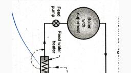
•, , Cooling Water Circuit: Abundant quantity of water is required for condensing, steam in the condenser. The water from the river is passed through the condenser., Sea water may also be used for this purpose. If adequate quantity of water is not, available at the plant sites, the warm water coming out from the condenser is, passed through the cooling tower where it is cooled with the help of air current. The, direct river system is known as open cooling water system, while the other is known, as closed cooling water system. The closed system is costlier among the two., , Basic components of thermal power plant, Working of the Thermal Power Plant, •, , •, , •, , •, , Steam is generated in the boiler of the thermal power plant using the heat of the fuel, burned in the combustion chamber. The steam generated is passed through steam, turbine where part of its thermal energy is converted into mechanical energy, which, is further used for generating electric power., The steam coming out of the steam turbine is condensed in the condenser and the, condensate is supplied back to the boiler with the help of the feed pump and the, cycle is repeated., The function of the boiler is to generate steam. The function of condenser is to, condense the steam coming out of steam turbine at low pressure. The function of, the steam turbine is to convert part of heat energy of steam into mechanical energy., The function of the pump is to raise the pressure of the condensate from the, condenser pressure (0.05 bar) to boiler pressure of 100 bar. The super heater and
Page 10 :
economizer used in the primary circuit to improve the overall efficiency of the, power plant., NUCLEAR POWER PLANTS, When water resources are not available, and thermal resources are inadequate in the, country to meet the power demand, the only solution is to adopt nuclear technology. This is, because; the transportation of nuclear fuel is easy as the quantity required is very less, compared with coal and oil., , Nuclear Energy, , •, , •, , •, , •, , The thermal energy generated by nuclear fuel is extremely large compared with, chemical fuels. The atomic structure of the nuclear fuel is different than chemical, fuels., In the nucleus of the nuclear fuel, the neutrons and protons are kept together in, compact form and energy required to keep them in bounded form is extremely large, and known as binding energy., In case of nuclear reactor, the nucleus of atom is broken by bombarding high energy, neutron from outside and the binding energy is released and is available in heat, form. This released energy is 106 to 107 times more compared with chemical energy., The high velocity neutrons coming out from broken atom are captured by the other, atoms of the fuel and other atoms are further broken. In this way, for each broken, atom, the number of neutrons coming out are more than the attacking neutrons and, therefore this is known as atomic chain reaction., , NUCLEAR REACTOR
Page 11 :
Components of the Nuclear reactor, Fuels: The fuels commonly used are natural uranium containing 0.7% 92U235 or enriched, uranium containing 2.5 % 92U235. The fuel is used in the form of rods or plates and, moderator surrounds the fuel element. The fuel rods are clad with stainless steel or, zirconium to prevent its oxidation. The fuel rods are arranged in cluster, and the complete, assembly is known as the core. The fuels which are used in nuclear reactor are 92U235, 92U233, (natural fuels) and 94Pu239 (artificial fuel), Moderator: The function of the moderator is to reduce the energy of neutrons evolved, during fission from about 2 meV to 0.25 eV in order to maintain the fission chain reaction., By slowing down high energy neutrons, the possibility of escape of neutrons is reduced and, possibility of absorption of neutrons by fuel to cause further fission is increased. This also, reduces the quantity of fuel required to maintain a chain reaction. The common, moderators used are ordinary water, heavy water and graphite., Reflector: The neutrons which may escape from the core without taking part in fission can, be reflected back into the core to take part in the fission reaction. This is generally done by, a reflector. The surface of the core of the reactor is covered with a moderator material, which reflects the escaping neutrons back into the core. The required properties of a good, reflector are low neutron absorption, high capacity to reflect and resistance to oxidation, and irradiation. The moderators, which are commonly used, also work as reflectors., Coolant: The purpose of the coolant is to transfer the heat generated in the reactor core, and use it for steam generation. The coolant circulated in the reactor keeps the, temperature of the fuel below safe level by continuous removal of energy from the core., The coolant used must have high specific heat to carry more heat per kg of coolant, circulated. It should not absorb neutrons. It must be non-corrosive, non-oxidizing and nontoxic. Ordinary water, heavy water, CO: are the common coolants used in power reactors.
Page 12 :
Control Rods: The purpose of the control rod is to maintain the value of multiplication, factor as one, that is to allow only neutron evolved in each fission to take part in further, fission reaction, just maintaining the chain. This maintains steady state heat generation in, the reactor. The control rod helps to vary the output according to the load and shut down, the reactor under emergency conditions. When shutting down of reactor is required, the, control rods absorb more number of neutrons than emitted and the fission reaction dies, out. The materials which are commonly used for control rods are cadmium, boron, or, hafnium. The control rod materials must have very high absorption capacity for neutrons., The control rods are generally operated automatically., Shielding: The reactor is a source of intense radioactivity and these radiations are very, harmful to the human life. Therefore, it is necessary to prevent the escape of these, radiations to the atmosphere. A thick concrete lining outside and inner thin lining of steel, are provided to prevent the radiations going to atmosphere., TIDAL POWER PLANT, •, , •, , •, , In this type of the power plant, tide of the sea is used for running the water turbine., The ocean tides contain large amount of potential energy which is used for power, generation., During the high tide period, the water flows from sea into the tidal basin through the, water turbine as the level of the tide is more than the water level in the tidal basin., This operates the turbine and ultimately the generator., During the low tide period, the water flows from tidal basin to sea as the water level, in the basin is more than that of the tide in the sea. During this period also, the, flowing water turns turbine and generates the power. The generation of power, stops only when sea level and tidal level are equal., , Advantages:, •, •, •, , It is free from pollution., It does not depend on rain., As it is located at sea-shore, it does not require valuable land.
Page 13 :
•, , It is very suitable to meet peak power demand., , Disadvantages:, •, •, •, •, , The output is not uniform due to variation in tidal range., The capital cost (Rs./kW) is very high compared with conventional hydel power, plants., There is more danger of corrosion of machine parts because of salty water. This, requires special materials for equipments which further increase the capital cost., As the power plant is located far away from the load centre, the transmission cost is, also high., , WIND POWER PLANT, •, •, , •, , This is another perennial source of energy. Wind flow is created as an effect of solar, heat which creates low and high pressure regions on the earth due to heating., The flowing wind (which has enough kinetic energy) is used to rotate the wind, turbine which is also known as wind mill. The wind mill can be directly coupled to a, generator to produce electrical power or the mechanical work of wind turbine can, be used to lift water for irrigation purposes., , Such a system is used for small power generation capacity. The biggest wind mill, erected for power generation is of 2500 kW capacity in USA. This source of energy is, gaining an importance throughout the world due to increasing price of fuels. The, fluctuation of wind velocity is the main drawback of this power generating system., Therefore, some form of storage of energy is essential to maintain a constant supply, of power.
Page 14 :
•, , There is a considerable scope of harnessing wind power to meet the growing, demands for energy in the rural parts of India. Some parts of Gujarat and Tamil, Nadu are considered as suitable sites for putting up wind mills to generate power on, a small scale., , Advantages, •, •, •, •, , This energy is available free of cost and renewable in nature., This is non-polluting source of energy., No fuel is required, so the question of transportation does not arise., The cost of generation is considerably low., , Disadvantages, •, •, •, •, •, , It does not provide constant output as wind velocity does not remain constant., It requires storage system as output is variable., It is more noisy., The weight of the system (kg/kW) is high., This is difficult to erect., , GEOTHERMAL POWER PLANT, •, , It is also a thermal power plant, but the steam required for power generation is, available naturally in some part of the earth below the earth surface., , Geothermal power plant, •, , It is a well known fact that the core of the earth is considerably hot. It has been, found that earth contains big reservoirs of steam which are created due to the, absorption of core heat by percolating water. Such steam is brought to the surface
Page 15 :
•, , •, , •, , •, , by drilling wells and then used for power generation. The exhaust steam coming out, of the turbine is either exhausted to atmosphere or condensed and pumped back, into the earth., The steam is tapped from the natural storage through a drilled well and then, supplied to the turbine passing through the separator where most of the dirt and, sand carried by the steam is removed., Then the steam is used to run the turbine which in turn drives the generator. The, exhaust steam coming out of the turbine is let into atmosphere. Therefore, this, system works on an open cycle. In many cases, the steam is condensed and the, condensate is pumped into the earth to absorb the ground heat again and to get, converted into steam., Another form of heat source under ground is hot rocks. To absorb the heat from, these hot rocks, wells are drilled into porous rocks at a depth of few kilometres and, water is circulated into the webs and taken back as steam and then used for power, generation., There is no geothermal power plant presently in India, but there are proposals to, put up a geothermal plant in Ladakh, , Advantages:, •, •, •, •, , It is less polluting compared with conventional thermal power plants., The components required are less as steam is readily available and therefore, the, capital cost (Rs./kW) is less., It provides flexibility in operation., The generating cost is less., , Disadvantages:, •, •, •, , Overall efficiency is less as the pressure of steam available is less., Difficult to locate and bring in operation., The steam carries a lot of foreign materials which are to be removed before its use., , SOLAR POWER PLANT, •, , •, , •, I., , The solar energy, which falls on the earth, is at a considerably low density and, therefore it cannot be used directly for power generation. The energy has to be, collected in a fluid so that it can be used to run an engine., The equipment which is used to collect and concentrate the solar energy and, increase the temperature of the working fluid is known as concentrating collectors., The collectors which are used in practice are classified as flat plate collectors and, concentrating collectors., These two types of collectors, Flat plate collector
Page 16 :
II., , Parabolic concentrated type collector, , •, , •, , •, , •, , •, , In flat plate collectors, the radiation energy falls on a flat surface which is coated, with paint having high absorbing capacity. The fluid (generally water) is circulated, through the flat plate collector and it carries the heat which falls on the collector, surface., In concentrator type of collector, the solar energy falling on the collector surface, is reflected and focussed along a line where the absorber is located. As the large, quantity of energy falling on the collector surface is collected over a small surface,, the temperature of the absorber fluids is considerably higher than in flat plate, collectors., Flat plate collectors are successfully designed to heat water upto 80°C. The, concentrating type of collectors are also designed to heat water to a higher, temperature or even to generate steam at lower pressures (2 to 2.5 bar)., As water boils only at 100°C at atmospheric pressure, it is not convenient to use it, with low temperature collectors. There are other fluids (ammonia and freon-12), which boil at lower temperature (40 to 50°C) at moderate pressures., Therefore, hot water at 80°C coming out of solar collector can be used to generate, vapours of ammonia or freon at higher pressure and the high pressure vapour can, be further used to rotate a turbine to develop the power, , The basic components of solar power plant using hot water coming out of the, collector as a source of energy are shown in Fig
Page 17 :
•, , The water heated in solar collector to 80°C is used for boiling the freon-12 at high, pressure in the freon boiler. The vapour generated at high pressure is used to run, the vapour turbine which drives the electrical generator., The vapor coming out of the turbine at lower pressure is condensed in a condenser, with the help of water at atmospheric temperature. The condensed liquid-freon is, fed back to the freon boiler with the help of the feed pump., The energy available from the sun throughout the day is not constant, therefore,, there must be some energy storage system which will store the hot water produced, when the sun is shining and use the same during cloudy weather or night time., , •, , •, , GRADES OF ENERGY, There are two types, I., II., , Low grade, High grade energy, , Based on the thermodynamic concepts, an energy source can be called as high-grade or, low-grade, depending the ease with which it can be converted into other forms., •, •, , Electrical energy is called a high-grade energy, as it is very easy to convert, almost all of it into other energy forms such as thermal, It is not possible to convert thermal energy completely into electrical energy, (typical efficiencies of thermal power plants are around 30 percent), hence, thermal energy is called a low-grade energy., , Energy Conversion Devices, PUMP
Page 18 :
•, •, , •, , These are hydraulic machines which convert mechanical energy into hydraulic, energy., Energy is utilized for lifting purposes or for increasing the pressure. Pumps are, driven by some prime mover which can be an I.C. engine, steam engine or an electric, motor., In most of the cases pump is used for raising fluids from a lower to a higher level., This is achieved by creating a low pressure at the inlet or suction end and high, pressure at the delivery end or outlet of the pump., , The pumps are classified as follows, I., II., , Reciprocating pumps, Centrifugal pumps, , Reciprocating Pumps- It consists of a piston or a plunger reciprocating inside a cylinder., The piston performs the suction and delivery strokes. These types of pumps deliver the, same quantity of liquid against any head. A reciprocating pump works at low speed., , Piston Pump, •, •, •, , •, , A single acting piston pump is shown in the Fig., As the piston moves outwards (towards right in the figure) partial vacuum will be, created inside the cylinder., The atmospheric pressure, acting on the surface of the liquid, forces it to pass, through the suction pipe into cylinder. Liquid will enter the cylinder through the, suction valve which will open into it., When the piston moves backwards (inward stroke), the piston will compress the, liquid in the cylinder and the pressure of the liquid will rise. This increased pressure, of the liquid will automatically close the suction valve and open the delivery valve, and the liquid will be pushed through the delivery pipe.
Page 19 :
DOUBLE ACTING PISTON PUMP, •, , •, , •, , In double acting piston pump, in every stroke, there is suction on one side and, delivery on the (left side) other side. When it moves from left to right, on the left, side of the piston, there is suction and on the right side there is delivery., When it moves from right to left, on the right side of the piston, there is suction and, on the left side there is delivery. A double acting piston pump is shown in Fig. It has, got two suction and two delivery pipes., Reciprocating pumps move the fluid using one or more oscillating pistons, plungers,, or membranes (diaphragms), while valves restrict fluid motion to the desired, direction., , CENTRIFUGAL PUMPS, In a centrifugal pump, we create pressure with the help of a centrifugal action. The pump is, driven by power from an external source by means of which the vanes are rotated. This, creates a centrifugal head of water in the pump. The water leaves the vanes with a high, velocity and pressure.
Page 20 :
A partial vacuum is created at the centre, due to which the water will be drawn through the, suction pipe. The high pressure created by the pump is utilized in overcoming the delivery, head of the pump. Discharge., , Centrifugal pump, •, •, , The rotating element of a centrifugal pump is called the impeller., Centrifugal pumps are usually of the radial-flow type, but pumps having a mixed, flow and axial flow are also made. Axial flow pumps are known as propeller pumps, and are used for low heads., , WORKING MECHANISM OF A CENTRIFUGAL PUMP, A centrifugal pump is one of the simplest pieces of equipment in any process plant. Its, purpose is to convert energy of a prime mover (an electric motor or turbine) first into, velocity or kinetic energy and then into pressure energy of a fluid that is being pumped.
Page 21 :
The energy changes occur by virtue of two main parts of the pump, the impeller and the, volute or diffuser. The impeller is the rotating part that converts driver energy into the, kinetic energy. The volute or diffuser is the stationary part that converts the kinetic energy, into pressure energy., General Components of Centrifugal Pump, A centrifugal pump has two main components:, 1. A rotating component comprised of an impeller and a shaft, 2. A stationary component comprised of a casing, casing cover, and bearings., , Stationary Components, Casing: Casings are generally of two types:, Volute and circular- The impellers are fitted inside the casings., Volute casings build a higher head, circular casings are used for low head and high capacity., A volute is a curved funnel increasing in area to the discharge port as shown in Fig.As the, area of the cross-section increases, the volute reduces the speed of the liquid and increases, the pressure of the liquid., One of the main purposes of a volute casing is to help balance the hydraulic pressure on the, shaft of the pump. However, this occurs best at the manufacturer's recommended capacity., Suction and Discharge Nozzle: The suction and discharge nozzles are part of the casing, itself., Gland: The gland is a very important part of the seal chamber or the stuffing box. It gives, the packings or the mechanical seal the desired fit on the shaft sleeve. It can be easily, adjusted in axial direction., Rotating Components
Page 22 :
Impeller: The impeller is the main rotating part that provides the centrifugal acceleration, to the fluid. They are often classified in many ways., , Based on major direction of flow in reference to the axis of rotation, 1. Radial flow, 2. Axial flow, 3. Mixed flow, , Based on mechanical construction, 1. Closed: Shrouds or sidewall enclosing the vanes, 2. Open: No shrouds or wall to enclose the vanes., , Semi-Open or Vortex Type: Centrifugal pumps are the ultimate in simplicity. In general,, there are two basic requirements that have to be met at all the times for a trouble free, operation and longer service life of centrifugal pumps. The first requirement is that no, cavitation of the pump occurs throughout the broad operating range and the second
Page 23 :
requirement is that a certain minimum continuous flow is always maintained during, operation., , COMPRESSORS, •, , •, , Compressed air is widely used in industry and in commercial equipments. It is very, commonly used for the operation of pneumatic drills, riveters, hammers, hoists,, paint spraying and many other operations., The object of an air compressor is to raise the pressure of air with the minimum, expenditure of energy. An air compressor sucks air from the atmosphere,, compresses it and delivers the same to the storage tank. From the storage tank, it is, conveyed by the pipelines where the supply of compressed air is needed. A, compressor has to be driven by some prime mover (diesel engine, electric motor) as, compression of air requires some work to be done on it., , Working of Single-Stage Reciprocating Air Compressor, , •, , •, , A reciprocating compressor consists of a cylinder, piston, crank shaft, connecting, rod, inlet and outlet valves as shown in Fig. During the downward motion of the, piston, the pressure inside the cylinder falls below the atmospheric pressure and, the spring loaded inlet valve is opened due to the pressure difference. The air is, drawn into the cylinder until the piston reaches the bottom dead centre position., As the piston starts moving upwards, the inlet valve is closed and the pressure starts, increasing continuously until the pressure inside the cylinder is above the pressure, of the delivery side which is connected to the receiver. Then the delivery valve
Page 24 :
opens and air is delivered to the receiver during the remaining upward motion of, the piston. At the end of the delivery stroke, a small volume of high pressure air is, left in the clearance space. The high pressure air left in the clearance expands as the, piston starts moving downwards and the pressure of the air falls until it is just, below the atmospheric pressure. The inlet valve then opens as the pressure inside, the cylinder falls below atmospheric pressure and the air from atmosphere is taken, in and the cycle is repeated. The suction, compression and delivery of air takes place, within two strokes of the piston or one revolution of the crank. The suction takes, place during one stroke and compression and delivery take place during the second, stroke., Classification of Reciprocating Air Compressor, 1. Single Acting: Single Cylinder Compressor In this compressor, the air is taken in at, pressure Pi and compressed to the required pressure and delivered to the receiver, at a higher pressure (P2). The delivery is once in one revolution of the compressor., 2. Single Cylinder: Double Acting Air Compressor: In this case, the top and bottom of, the piston are used for suction, compression and delivery of the air. Therefore,, delivery is twice in one revolution of the compressor and the mass of air delivered is, twice the mass of air delivered by single acting-single cylinder compressor., 3. Single Acting, Multicylinder Compressor: It consists of 'n' number of cylinders, mounted on the same shaft and each cylinder works similar to single cylinder, compressor. The mass delivered by the compressor is 'n' Armes the mass delivered, by single cylinder compressor. The arrangement can be made as double acting for, each cylinder. The purpose of this arrangement is to deliver more quantity of air at, the same pressure., 4. Multistage Compressor: This is generally used when the required delivery, pressure (p3) is considerably high. The delivery of the first cylinder becomes the, suction of the second cylinder. The diameter of the second cylinder (d) is less than, the first cylinder (D) as the mass of air in the second cylinder occupies less volume, than the volume occupied in the first cylinder by the same mass as p2 > pi, , Multistage Compressors, Uses of Compressed Air
Page 25 :
•, •, •, •, •, •, •, , Compressed air is used to charge the automobile tires., It is also used for air-washing the vehicles in the service stations., It is used in operating lifts and hoists., It is used for operating air brakes in automobiles and locomotives., It is used in spray-painting., It is very commonly used in sand blasting industries., It is used in air-lifted pumps to pump the water from deep-bores., , TURBINE, Turbines absorb the energy in falling water and make it available for useful work. It, changes the hydraulic or potential energy into mechanical power. The turbine drives the, generator which converts the mechanical energy into electrical energy., Classification Water turbines are divided into two main classes as, (a) Impulse turbines. (b) Reaction turbines, Impulse turbines, The water may be admitted over part of the circumference only or over the whole, circumference. The impulse turbine may be radial flow or axial flow turbine. The pelton, wheel is a type of impulse turbine., Pelton Wheel :, •, , •, , •, , •, , •, , •, , The pelton wheel, also called pelton turbine. It is the special type of axial flow, impulse turbine generally mounted on a horizontal axis. It can also be mounted with, its axis vertical., It operates under a high head of water and therefore, requires a comparatively less, quantity of water. Water is conveyed in penstocks from the head race in the, mountains to the turbine in the power house., The penstock is joined to a branch pipe or lower bends fitted with a nozzle at the, end. Water comes out of nozzle in the form of a free and compact jet at a very high, velocity., The number of nozzles required for a turbine depends on its specific speed. The, water having a high velocity is made to impinge, on buckets fixed round the, circumference of a wheel, the latter being mounted on a shaft., The impact of water on the surface of the bucket produces a force which causes the, wheel to rotate, thus supplying a torque or mechanical power on the shaft. The jet of, water strikes the double hemispherical cup-shaped buckets at the centre and is, deviated on both sides, thus eliminating an end thrust., After performing work on the buckets, water is discharged into the tail race. The, wheel must be so located that the buckets do not splash into the tail race water
Page 26 :
when it revolves. Overall efficiencies are obtained upto 88 per cent and single, wheels have been constructed to produce 50 MW power., , REACTION TURBINE, •, , •, , In the reaction turbine, water enters the wheel under pressure and flows over the, vanes. In passing over the vanes, the pressure head is converted to velocity head, and is finally reduced to atmospheric pressure before leaving the wheel. The water, leaves the wheel with a large velocity but a small absolute velocity, practically the, whole of its original energy has been given to the wheel., In reaction turbine, total head consists partly of pressure head and partly of velocity, head. As the water is under pressure, the wheel must run full and may, therefore, be, entirely submerged below the tail race., , Francis turbine, •, , •, •, , •, , The Francis turbine is an inward flow radial reaction type. The water under, pressure, enters the runner from the guide vanes towards the centre in radial, direction and discharges out of runner axially., It operates under medium heads and also requires medium quantity of water., A part of the head acting on the turbine is transformed into kinetic energy and the, rest remains as pressure head. There is a difference of pressure between the guide, vanes and the runner which is called the reaction pressure and is responsible for the, motion of the runner., That is why a Francis turbine is also known as reaction turbine. In this turbine, the, pressure at the inlet is more than that at the outlet. In the Francis turbine, the, runner is always full of water. After doing work, the water is discharged to the tail, race through a draft tube. The free end of the draft tube is submerged deep in the, tail race.
Page 27 :
Kaplan Turbine:, •, , •, , •, , The Kaplan turbine is a reaction turbine. It operates in an entirely close conduit, from inlet to tail race. The turbine is used where comparatively low head and large, quantity of water is available., All parts such as spiral casing, guide mechanism and draft tube of the Kaplan turbine, except the runner are similar to those of Francis type. In Kaplan runner, it strikes, the blades axially. Number of blades in Kaplan turbine is only 3 to 6 or at the most 8, in exceptional cases., This reduces the contact surface with water and hence the frictional resistance., Kaplan blades are attached to the boss, dispensing with the band, thus eliminating, the frictional losses likely to be caused by the latter. A single unit can produce an, output of 30-50 MW. The specific speed varies between 80 to 240., , WIND MILLS, The wind mill generator units convert wind power into electrical power. The wind passes, through the propeller and producing the circumferential force and axial thrust. This, circumferential force also known as torque, converts the wind power to mechanical rotary, power, which drives the generator to produce the electrical power., The wind mills are classified, 1. Horizontal axis wind turbine, 2. Vertical ads wind turbine, Horizontal axis wind turbine, •, •, , Horizontal axis wind turbines are of monoblade type, twin bladed and three blade, type the propeller are of two types (a) Upwind type (b) Downwind type., In upwind type the blades are slanted and wind approaching the blades from front, side and nacelle is placed on rare side of the blade. Nacelle has propeller, gears and, generator. In downwind design wind approaches blades from nacelle side.
Page 28 :
•, , •, , •, , The monoblade wind turbine has lighter rotor. The blades are lighter in weight,, Length of blade varies from 15m to 25m. For extremely large blade a counter weight, is used to balance the blade centrifugally, otherwise bending moments may occur, due to gravity and sudden change in wind direction., In twin blades, horizontal axis wind turbine has two blades. Two blades design face, the difficulty of vibration. At higher wind speeds, the forces on blade in upper, position are higher than the forces on blade in lower position. Due to this difference, in forces, rotor experiences severe vibrations, which causes failure during, orientation of nacelle. To avoid this, tethering control is provided., In three blades, the rotor has three blades. It is not necessary to provide tethering, controlling three blades. The blades are long and mounted on hub. The shaft is, mounted on bearing. The step up gear box changes the speed of turbine shaft to the, required speed of generator. The generator, turbine, bearing are mounted in nacelle., The position of nacelle changes automatically according to the direction of wind., , Vertical axis wind turbine, •, , •, , •, , These are also known as cross-wind axis machine. Here the axis of rotation is, perpendicular to the direction of the wind. It has been found that the vertical type of, wind-turbine, are lighter in weight and cheaper in cost, Further they are omni directional and do not require a heavy shaft to support the, rotor. Because of Omni directionality they do not need the yaw control to orient the, rotor axis in the direction of wind., Vertical ads wind turbine captures wind in any direction, therefore tall tower and, long blades are not required. In this type of machine, the generator can be placed at, base level or within the support tower. Nacelle is also not required in vertical axis, wind turbine

