Page 1 :
TPS, TPS, ELECTRONICS - I, (39 TOPICWISE PAPERS SOLUTION FROM, MARCH 2001 TO UPTO DATE), SALIENT FEATURES, 1., Simple and lucid language., To the point answers, according to New Syllabus., Topicwise paerps, Objective questions and problems with solutions are given separately for each chapter., Problems for practice are given for each chapter., Board's Question Papers from March 2001 to upto date are given and chapter number and, question number are mentioned for self checking by the students., 2., 3., solutions of all board question papers from March 2001., 4., 5., 6., Price : 160/-, KINNARI PRAKASHAN, 8, Santoshi Mata C.H.S., Dr. D.B. Marg, Mumbai- 8. Cell : 98901 33079, 98606 45722, Website : www.kinnariprakashan.com, www.tpsbooks.com, 1
Page 2 :
internet or otherwise) without prior written permission of the Author or, Electronics - Paper I (Applied Electronics) - Contents, Title, Page No., CH. No., 1-1 to 1-20, Instruments, 2-1 to 2-43, 2., Power Supplies, Transducers, 3-1 to 3-13, 4-1 to 4-39, 4, Operational Amplifiers, Modern Electronic Communications, 5-1 to 5-40, Study of Integrated Circuits, Question Papers from March 2001 to Upto date, 6-1 to 6-21, 6., Q-1 to Q-85, MOS Chapterwise Marking Scheme Paper I, ETAC Chapter No. % Marks, 15, 20, 3., 10, 4, 25, 20, 6., 10, Scheme of Examination for Electronics, Termwork Total, Marks, Paper, Practical, Theory, Marks, Time, Marks, Time, Marks, 50, 3 Hours, 30, 3 Hours, 20, 100, II, 50, 3 Hours, 30, 3 Hour, 20, 100, © Copy Right Reserved : All rights reserved. No part of this publication may, be reproduced, stored in or introduced into a retrieval system transmitted in, any form by any means (Electronic, Mechanical, Photocopying, recordng, Publishers., Published By, MAR. Maroo, Kinnari Prakashan,, 58/60, D.B. Marg, Mumbai - 8, Printed at :, ARIHANT, Pune - 30, 2
Page 3 :
Instruments, ОВЈEСTIVES, 1), If the Lissajous pattern seen on the CRT screen is a circle, then the phase difference, between the two signals is...., (March 2001), i) 0°, ii) 90°, iii) 180°, iv) 45°, 2), Deflection sensitivity of a CRT is measured in..., (March 2003), ) Ω/volt, ii) volts/2 iii) mm/volt, iv) none of these, 3), In function generator for the generation of triangular wave.. circuit is used., i) Integrator, ii) Schmitt Trigger, (March2004), iii) Resistance diode waveshaping, iv) Differentiator, 4), DMM measures...value of A.C. voltage., (Oct. 2005), i) RMS, ii) Peak, iii) Average, iv) none of these, 5), If a Lissajous pattern like 8 is obtained, then frequency to vertical input fy and frequency, to horizontal input f, are related by the equation .., (March 1999, 2006), i) fy = 2f,, ii) fy = 2f,, iii) fy = fy, iv) none of these, 6), In CRT ....., anode has variable positive voltage., (Oct. 2008), ii) focussing, In CRO intensity of spot can be controlled by changing.., i), pre - accelerating, iii) accelerating, iv) control grid, 7), (Oct. 1995), ......, 8), If retrace path is visible on CRO screen, then the fault is in., (Oct. 1992), If the negative potential on control grid of CRT is increased then the intensity of electron, (March1991), In CRO, a sawtooth voltage developed by the time-base generator is applied to...., (Oct. 1986, 2010), 9), beam ..., 10), 11) If a voltage of 1000 volts is applied to the vertical plates of CRO, it produces a vertical, shift of 5 mm of the spot, hence the deflection sensitivity is .., (March 1986), 12), The time base signal in CRO is, (Oct. 1988), ...... wave., Ans. 1), 90°, 2), mm/volt, 3) Integrator, 4), RMS, 5) f = 2f,, 6), focussing, 7) grid potential, 8) Blanking circuit, 9), decreases, 10) horizontal X deflection plates, 11) 0.005 mm/volt, 12) saw-tooth, 3
Page 4 :
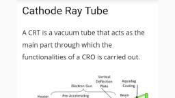
Instruments, 1.2, TPS Electronic Paper - I, (Oct. 1996), 13), DVM displays measurement of voltage as .., In CRO the colour of bright spot on the screen depends on ..., 14), In DMM, ±0.005 % indicates...., accuracy., 15), 16), In most of DMMS, 1 is displayed to indicate, The instrument which provides sine, square and triangular waveforms is called., is used., 17), In single beam dual trace CRO, principle of, signal., 18), 19), The calibration signal, usually available from a CRO, is a ....., of SYNC. control in CRO is to ..., The, 20), A non-triggered oscilloscope is one which., The secondary electrons produced in CRT are collected by, (i) Graphite Coating, (iii) Secondary Anode, In CRO the Lissajous Figure Method can be used for measurement of, purpose, 21), (July 2016) (1), 22), (ii) Phosphorous Coating, (iv) All of the above, 23), (i) Frequency, (iii) Resistance, (ii) Current, (March 2017) (1), (iv) None of these, Ans. 13) material used for coating of CRT screen., 16) over-range, 15) high, 18) electronic switching 19) square wave, 14) discrete numerals, 17) function generator, 21) has a continuously running time-base generator, 23) Frequency, 20) lock the display of the signal, 22) Graphite coating, Cathode Ray Oscilloscope, Draw labelled diagram of Cathode Ray Tube and explain function of each electrode, (part) in it., Q.1, (4 Marks), (March 2003, 05, 07, 10, 12, 13, 14, 15, 19; Oct. 2003, 04, 05, 15, July 2017), Ans.:, Pre-accelerating, Vertical, Annde, Focussing Def., Annde Plates, Pins Base, Horizontal Def. Plates, Filament, Electron, Beam, Fluorescent, Screen, Cathode, Accelerating Annde, Aquadag, Coating, Control Grid, Hlectron Gun, Deflection Plate, Annembly, /-, Assembly, Fig. 1.1: Cathode Ray Tube (CRT), 4
Page 5 :
TPS Electronic Paper I, 1.3, Instruments, Main parts of Cathode Ray Tube (CRT) are:, 1), Electron gun assembly, 2), Deflection plate assembly, Fluorescent screen and, 3), CRT is the heart of CRO. The electron gun assembly produces a narrow and sharply, focussed beam of electrons which travels with a very high velocity towards the fluorescent, screen. On its way the beam passes through two pairs of deflection plates. On striking the, screen, the beam produces a small light spot on the screen., Electron gun - Electrons are emitted from an indirectly heated cathode. The cathode is, surrounded by a control grid. The electrons that pass through small hole in grid make, up beam current. The magnitude of beam current can be adjusted by INTENSITY, control. The electrons are then accelerated by high positive potential applied to two, accelerating anodes. These anodes are separated by a focussing anode which provides a, narrow and sharp electron beam. The beam then travels through deflection plate, assembly., Deflection Plate Assembly - If voltages are applied to the deflection plates, the electron, beam can be deflected in horizontal direction by horizontal deflection plates or in, vertical direction by vertical deflection plates. Mostly electrostatic deflection is used in, 4), Glass envelope and base of the tube., 1., 2., CRT., Fluorescent Screen When electron beám strikes the screen of the CRT, a spot of light is, produced. On the inner surface of screen, phosphor coating is present. The secondary, electrons are collected by a conductive coating called as Aquadag which is electrically, connected to the second anode., 3., Glass Envelope and base of the tube : The envelope of CRT is made of glass. It is highly, evacuated. The elements of the electron gun assembly are connected to pins on the CRT, 4., base., Q. 2 Explain electrostatic focussing system of a CRT., (March 2008, 11, 13, 16, 18, Oct. 2003, 14), Ans. :, Preaccelerating, anode, Focusing Accelerating, anode, Control grid, anode, Screen, + High voltage, supply, Focus, Fig. 1.2: Electrostatic focussing system of CRT, The electrostatic focussing system of CRT consists of preaccelerating anode, focussing, anode and accelerating anode. These anodes are cylindrical in form, with small openings, located in the centre of each cylinder, along the axis of the tube. The electrons coming out of, the control grid are accelerated by the high voltage applied to the accelerating anode. These


