Page 1 :
DRAWINGS:, ( A Graphical Representation), The Fact about:, If compared with Verbal or Written Description,, Drawings offer far better idea about the Shape, Size & Appearance of, any object or situation or location, that too in quite a less time., Hence it has become the Best Media of Communication, not only in Engineering but in almost all Fields., , Prepared By:, , Er.Meraj Alam Idrisi, Department of Mechanical Engineering, Town Polytechnic, Ballia
Page 2 :
Drawings, (Some Types), , Botanical Drawings, ( plants, flowers etc.), , Nature Drawings, ( landscape,, Geographical, scenery etc.), Drawings, ( maps etc.), , Building Related Drawings., , Orthographic Projections, (Fv,Tv & Sv.-Mech.Engg terms), (Plan, Elevation- Civil Engg.terms), (Working Drawings 2-D type), , Portraits, ( human faces,, expressions etc.), , Zoological Drawings, (creatures, animals etc.), , Engineering Drawings,, (projections.), , Machine component Drawings, , Isometric ( Mech.Engg.Term.), or Perspective(Civil Engg.Term), (Actual Object Drawing 3-D)
Page 3 :
SCALES, DIMENSIONS OF LARGE OBJECTS MUST BE REDUCED TO ACCOMMODATE, ON STANDARD SIZE DRAWING SHEET.THIS REDUCTION CREATES A SCALE, OF THAT REDUCTION RATIO, WHICH IS GENERALLY A FRACTION.., SUCH A SCALE IS CALLED REDUCING SCALE, AND, THAT RATIO IS CALLED REPRESENTATIVE FACTOR., SIMILARLY IN CASE OF TINY OBJECTS DIMENSIONS MUST BE INCREASED, FOR ABOVE PURPOSE. HENCE THIS SCALE IS CALLED ENLARGING SCALE., HERE THE RATIO CALLED REPRESENTATIVE FACTOR IS MORE THAN UNITY., USE FOLLOWING FORMULAS FOR THE CALCULATIONS IN THIS TOPIC., , A, , REPRESENTATIVE FACTOR (R.F.) =, , =, =, , DIMENSION OF DRAWING, DIMENSION OF OBJECT, LENGTH OF DRAWING, ACTUAL LENGTH, AREA OF DRAWING, V ACTUAL AREA, , =3, , VOLUME AS PER DRWG., , V ACTUAL VOLUME, , B, , LENGTH OF SCALE = R.F., , X, , MAX. LENGTH TO BE MEASURED., , FOR FULL SIZE SCALE, R.F.=1 OR ( 1:1 ), MEANS DRAWING, & OBJECT ARE OF, SAME SIZE., Other RFs are described, as, 1:10,, 1:100,, 1:1000, 1:1,00,000
Page 4 :
BE FRIENDLY WITH THESE UNITS., 1 KILOMETRE, 1 HECTOMETRE, 1 DECAMETRE, 1 METRE, 1 DECIMETRE, 1 CENTIMETRE, , = 10 HECTOMETRES, = 10 DECAMETRES, = 10 METRES, = 10 DECIMETRES, = 10 CENTIMETRES, = 10 MILIMETRES, , TYPES OF SCALES:, 1., 2., 3., 4., 5., , PLAIN SCALES, ( FOR DIMENSIONS UP TO SINGLE DECIMAL), DIAGONAL SCALES, ( FOR DIMENSIONS UP TO TWO DECIMALS), VERNIER SCALES, ( FOR DIMENSIONS UP TO TWO DECIMALS), COMPARATIVE SCALES ( FOR COMPARING TWO DIFFERENT UNITS), SCALE OF CORDS, ( FOR MEASURING/CONSTRUCTING ANGLES)
Page 5 :
ORTHOGRAPHIC PROJECTIONS:, IT IS A TECHNICAL DRAWING IN WHICH DIFFERENT VIEWS OF AN OBJECT, ARE PROJECTED ON DIFFERENT REFERENCE PLANES, OBSERVING PERPENDICULAR TO RESPECTIVE REFERENCE PLANE, , Different Reference planes are, Horizontal Plane (HP),, Vertical Frontal Plane ( VP ), Side Or Profile Plane ( PP), , And, , Different Views are Front View (FV), Top View (TV) and Side View (SV), , FV is a view projected on VP., TV is a view projected on HP., SV is a view projected on PP., , IMPORTANT TERMS OF ORTHOGRAPHIC PROJECTIONS:, , 1 Planes., 2 Pattern of planes & Pattern of views, 3 Methods of drawing Orthographic Projections
Page 6 :
PLANES, , 1, PRINCIPAL PLANES, HP AND VP, , AUXILIARY PLANES, , Auxiliary Vertical Plane, (A.V.P.), , Auxiliary Inclined Plane, (A.I.P.), , A.V.P., ^ to Hp & Ð to Vp, , ^t, , Ð, , A.I, .P., , oV, & p, to, Hp, , Profile Plane, ( P.P.)
Page 7 :
PATTERN OF PLANES & VIEWS (First Angle Method), , 2, , THIS IS A PICTORIAL SET-UP OF ALL THREE PLANES., ARROW DIRECTION IS A NORMAL WAY OF OBSERVING THE OBJECT., BUT IN THIS DIRECTION ONLY VP AND A VIEW ON IT (FV) CAN BE SEEN., THE OTHER PLANES AND VIEWS ON THOSE CAN NOT BE SEEN., , PROCEDURE TO SOLVE ABOVE PROBLEM:-, , Y, , TO MAKE THOSE PLANES ALSO VISIBLE FROM THE ARROW DIRECTION,, A) HP IS ROTATED 900 DOUNWARD, B) PP, 900 IN RIGHT SIDE DIRECTION., THIS WAY BOTH PLANES ARE BROUGHT IN THE SAME PLANE CONTAINING VP., , X, , Click to view Animation, , On clicking the button if a warning comes please click YES to continue, this program is, safe for your pc., , PP, , VP, , Y, , FV, , LSV, , Y, , X, X, , TV, HP, , 0, , HP IS ROTATED DOWNWARD 90, AND, BROUGHT IN THE PLANE OF VP., , 900, , PP IS ROTATED IN RIGHT SIDE, AND, BROUGHT IN THE PLANE OF VP., , ACTUAL PATTERN OF PLANES & VIEWS, OF ORTHOGRAPHIC PROJECTIONS, DRAWN IN, FIRST ANGLE METHOD OF PROJECTIONS
Page 8 :
3, , Methods of Drawing Orthographic Projections, , First Angle Projections Method, Here views are drawn, by placing object, , Third Angle Projections Method, Here views are drawn, by placing object, , in 1st Quadrant, , in 3rd Quadrant., , ( Fv above X-y, Tv below X-y ), , (, SYMBOLIC, PRESENTATION, OF BOTH METHODS, WITH AN OBJECT, STANDING ON HP ( GROUND), ON IT’S BASE., , FV, , X, TV, , Y, , Tv above X-y, Fv below X-y ), , TV, , NOTE:-, , X, , 1st, , HP term is used in, Angle method, &, For the same, Ground term is used, in 3rd Angle method of projections, , Y, , FV, G, , L
Page 9 :
FIRST ANGLE, PROJECTION, , FOR T.V., , IN THIS METHOD,, THE OBJECT IS ASSUMED TO BE, SITUATED IN FIRST QUADRANT, MEANS, ABOVE HP & INFRONT OF VP., , OBJECT IS INBETWEEN, OBSERVER & PLANE., PP, , VP, FV, , LSV, , Y, , X, TV, HP, ACTUAL PATTERN OF, PLANES & VIEWS, IN, FIRST ANGLE METHOD, OF PROJECTIONS, , R, FO, , ., S.V, , FO, R, , F.V, .
Page 10 :
THIRD ANGLE, PROJECTION, , FOR T.V., , IN THIS METHOD,, THE OBJECT IS ASSUMED TO BE, SITUATED IN THIRD QUADRANT, ( BELOW HP & BEHIND OF VP. ), , PLANES BEING TRANSPERENT, AND INBETWEEN, OBSERVER & OBJECT., , TV, , X, , Y, LSV, , FV, , ACTUAL PATTERN OF, PLANES & VIEWS, OF, THIRD ANGLE PROJECTIONS, , R, FO, , ., S.V, , FO, R, , F.V, .
Page 11 :
ORTHOGRAPHIC PROJECTIONS, { MACHINE ELEMENTS }, OBJECT IS OBSERVED IN THREE DIRECTIONS., THE DIRECTIONS SHOULD BE NORMAL, TO THE RESPECTIVE PLANES., AND NOW PROJECT THREE DIFFERENT VIEWS ON THOSE PLANES., THESE VEWS ARE FRONT VIEW , TOP VIEW AND SIDE VIEW., FRONT VIEW IS A VIEW PROJECTED ON VERTICAL PLANE ( VP ), TOP VIEW IS A VIEW PROJECTED ON HORIZONTAL PLANE ( HP ), SIDE VIEW IS A VIEW PROJECTED ON PROFILE PLANE ( PP ), , FIRST STUDY THE CONCEPT OF 1ST AND 3RD ANGLE, PROJECTION METHODS, AND THEN STUDY NEXT 26 ILLUSTRATED CASES CAREFULLY., TRY TO RECOGNIZE SURFACES, PERPENDICULAR TO THE ARROW DIRECTIONS
Page 12 :
FIRST ANGLE, PROJECTION, , FOR T.V., , IN THIS METHOD,, THE OBJECT IS ASSUMED TO BE, SITUATED IN FIRST QUADRANT, MEANS, ABOVE HP & INFRONT OF VP., , OBJECT IS INBETWEEN, OBSERVER & PLANE., PP, , VP, FV, , LSV, , Y, , X, TV, HP, ACTUAL PATTERN OF, PLANES & VIEWS, IN, FIRST ANGLE METHOD, OF PROJECTIONS, , R, FO, , ., S.V, , FO, R, , F.V, .
Page 13 :
FOR T.V., , THIRD ANGLE, PROJECTION, IN THIS METHOD,, THE OBJECT IS ASSUMED TO BE, SITUATED IN THIRD QUADRANT, ( BELOW HP & BEHIND OF VP. ), , PLANES BEING TRANSPERENT, AND INBETWEEN, OBSERVER & OBJECT., , TV, , X, , Y, LSV, , FV, , ACTUAL PATTERN OF, PLANES & VIEWS, OF, THIRD ANGLE PROJECTIONS, , R, FO, , ., V, ., S, , FO, R, , F.V, .
Page 14 :
FOR T.V., , 1, , ORTHOGRAPHIC PROJECTIONS, , R, FO, , S.V, , ., , FO, R, , FRONT VIEW, , L.H.SIDE VIEW, , F., , V., , x, , PICTORIAL PRESENTATION IS GIVEN, DRAW THREE VIEWS OF THIS OBJECT, BY FIRST ANGLE PROJECTION METHOD, , y, , TOP VIEW
Page 15 :
FOR T.V., , 2, , ORTHOGRAPHIC PROJECTIONS, FRONT VIEW, , R, FO, , ., V, ., S, , FO, R, , X, , Y, , F.V, ., , TOP VIEW, , PICTORIAL PRESENTATION IS GIVEN, DRAW THREE VIEWS OF THIS OBJECT, BY FIRST ANGLE PROJECTION METHOD, , L.H.SIDE VIEW
Page 16 :
FOR T.V., , 3, , ORTHOGRAPHIC PROJECTIONS, FRONT VIEW, , R, FO, , ., S.V, , FO, R, , F., , V., , X, , Y, , TOP VIEW, , PICTORIAL PRESENTATION IS GIVEN, DRAW THREE VIEWS OF THIS OBJECT, BY FIRST ANGLE PROJECTION METHOD, , L.H.SIDE VIEW
Page 17 :
4, , FOR T.V., , ORTHOGRAPHIC PROJECTIONS, , FRONT VIEW, , R, FO, , ., S.V, , FO, R, , X, , Y, , F.V, ., , TOP VIEW, , PICTORIAL PRESENTATION IS GIVEN, DRAW THREE VIEWS OF THIS OBJECT, BY FIRST ANGLE PROJECTION METHOD, , L.H.SIDE VIEW
Page 18 :
FOR T.V., , 5, , ORTHOGRAPHIC PROJECTIONS, , R, FO, , FRONT VIEW, , ., V, ., S, FO, R, , PICTORIAL PRESENTATION IS GIVEN, DRAW THREE VIEWS OF THIS OBJECT, BY FIRST ANGLE PROJECTION METHOD, , F.V, ., , X, , L.H.SIDE VIEW, , Y, , TOP VIEW
Page 19 :
6, FOR T.V., ORTHOGRAPHIC PROJECTIONS, , FRONT VIEW, , R, FO, , ., V, ., S, , FO, R, , X, , Y, , F.V, ., , TOP VIEW, , PICTORIAL PRESENTATION IS GIVEN, DRAW THREE VIEWS OF THIS OBJECT, BY FIRST ANGLE PROJECTION METHOD, , L.H.SIDE VIEW
Page 20 :
7, FOR T.V., , ORTHOGRAPHIC PROJECTIONS, FRONT VIEW, , FO, R, , R, FO, , ., V, ., S, , L.H.SIDE VIEW, , F.V, ., , X, , PICTORIAL PRESENTATION IS GIVEN, DRAW THREE VIEWS OF THIS OBJECT, BY FIRST ANGLE PROJECTION METHOD, , Y, , TOP VIEW
Page 21 :
STUDY, Z, ILLUSTRATIONS, , 8, , FOR T.V., ORTHOGRAPHIC PROJECTIONS, , FRONT VIEW, 50, , X, , Y, , 20, , FO, R, , 25, , F.V, ., 25, , 20, , TOP VIEW, , PICTORIAL PRESENTATION IS GIVEN, DRAW THREE VIEWS OF THIS OBJECT, BY FIRST ANGLE PROJECTION METHOD
Page 22 :
9, FOR T.V., , ORTHOGRAPHIC PROJECTIONS, FRONT VIEW, , X, , R, FO, , ., S.V, , FO, R, , Y, , F.V, ., , PICTORIAL PRESENTATION IS GIVEN, DRAW THREE VIEWS OF THIS OBJECT, BY FIRST ANGLE PROJECTION METHOD, , L.H.SIDE VIEW, , TOP VIEW
Page 23 :
ORTHOGRAPHIC PROJECTIONS, , FOR T.V., , FRONT VIEW, , X, , FO, , L.H.SIDE VIEW, , Y, , .V., S, R, , R, FO, ., F.V, , PICTORIAL PRESENTATION IS GIVEN, DRAW THREE VIEWS OF THIS OBJECT, BY FIRST ANGLE PROJECTION METHOD, , 10, , TOP VIEW
Page 24 :
FOR T.V., ORTHOGRAPHIC PROJECTIONS, FRONT VIEW, , FO, R, , R, FO, , F.V X, ., , L.H.SIDE VIEW, , Y, , ., V, ., S, , TOP VIEW, , PICTORIAL PRESENTATION IS GIVEN, DRAW THREE VIEWS OF THIS OBJECT, BY FIRST ANGLE PROJECTION METHOD, , 11
Page 25 :
12, , FOR T.V., , ORTHOGRAPHIC PROJECTIONS, FRONT VIEW, , X, , R, FO, , ., S.V, , FO, R, , Y, , F.V, ., , PICTORIAL PRESENTATION IS GIVEN, DRAW THREE VIEWS OF THIS OBJECT, BY FIRST ANGLE PROJECTION METHOD, , L.H.SIDE VIEW, , TOP VIEW
Page 26 :
13, , STUDY, Z, ILLUSTRATIONS, , FOR T.V., ORTHOGRAPHIC PROJECTIONS, , 35, , FV, , 35, 10, , x, , 20, , 10, , FO, R, , O, , F.V, ., , PICTORIAL PRESENTATION IS GIVEN, DRAW FV AND TV OF THIS OBJECT, BY FIRST ANGLE PROJECTION METHOD, , 40, 70, , TV, , 30, , y
Page 27 :
STUDY, Z, ILLUSTRATIONS, , R, FO, , 14, , FOR T.V., , ORTHOGRAPHIC PROJECTIONS, FV, 30, , 10, , 30, , SV, , 30, 10, 30, , x, , ., S.V, , FO, R, , y, , F.V, ., , PICTORIAL PRESENTATION IS GIVEN, DRAW THREE VIEWS OF THIS OBJECT, BY FIRST ANGLE PROJECTION METHOD, , TV, , ALL VIEWS IDENTICAL
Page 28 :
OR, , STUDY, Z, ILLUSTRATIONS, , 15, ORTHOGRAPHIC PROJECTIONS, FOR T.V., ALL VIEWS IDENTICAL, FV, , SV, , y, , x, , 10, , ., S.V, , FO, R, , F.V, ., , PICTORIAL PRESENTATION IS GIVEN, DRAW THREE VIEWS OF THIS OBJECT, BY FIRST ANGLE PROJECTION METHOD, , 40, , 40, 60, , 60, , TV
Page 29 :
FOR T.V., , ORTHOGRAPHIC PROJECTIONS, , 16, , ALL VIEWS IDENTICAL, FV, , SV, , y, , x, 10, , R, FO, , ., V, ., S, , FO, R, , F.V, ., , PICTORIAL PRESENTATION IS GIVEN, DRAW THREE VIEWS OF THIS OBJECT, BY FIRST ANGLE PROJECTION METHOD, , 40, , 40, 60, , 60, , TOP VIEW
Page 30 :
17, ORTHOGRAPHIC PROJECTIONS, , FRONT VIEW, 40, , L.H.SIDE VIEW, 30 SQUARE, 20, , 50, , R, FO, , FO, R, , ., S.V, , F.V X, ., , 20, , 10, , O, , PICTORIAL PRESENTATION IS GIVEN, DRAW FV AND SV OF THIS OBJECT, BY FIRST ANGLE PROJECTION METHOD, , 30, , F.V., , 60, , S.V., , Y
Page 31 :
FOR T.V., , ORTHOGRAPHIC PROJECTIONS, , 18, , FV, 40, , X, , O, , 10, , Y, , 45, , 30 D, , FO, R, , F.V, ., , O, , 10, , 50, , 80, , TV, , PICTORIAL PRESENTATION IS GIVEN, DRAW FV AND TV OF THIS OBJECT, BY FIRST ANGLE PROJECTION METHOD
Page 32 :
19, , FOR T.V., , ORTHOGRAPHIC PROJECTIONS, , 40, , FV, , O, , X, , 10, , Y, , 100, 10, , FO, R, , 25, , TV, , 10, , 30 R, 20 D, , 30, , 10, , 25, , O, , F.V, ., , PICTORIAL PRESENTATION IS GIVEN, DRAW FV AND TV OF THIS OBJECT, BY FIRST ANGLE PROJECTION METHOD
Page 33 :
PICTORIAL PRESENTATION IS GIVEN, DRAW FV AND TV OF THIS OBJECT, BY FIRST ANGLE PROJECTION METHOD, , ORTHOGRAPHIC PROJECTIONS, , 30, , FOR T.V., FV, RECT., SLOT, , 10, , 50, , 35, , 10, , X, , 20 D, , FO, R, , F.V, ., , TV, , 60 D, 30 D, TOP VIEW, , O, , Y, , 20
Page 34 :
21, ORTHOGRAPHIC PROJECTIONS, 10, , 25, , 15, , 25, 40, , 10, 25, , R, FO, , FO, R, , ., S.V, , O, , F.V, ., O, , 25, 80, , F.V., , PICTORIAL PRESENTATION IS GIVEN, DRAW FV AND SV OF THIS OBJECT, BY FIRST ANGLE PROJECTION METHOD, , 25, , S.V.
Page 35 :
FOR T.V., ORTHOGRAPHIC PROJECTIONS, , 450, , 30, , FV, , 40, , X, , FO, R, , Y, 30 D, , F.V, ., TV, , 40, , O, , PICTORIAL PRESENTATION IS GIVEN, DRAW FV AND TV OF THIS OBJECT, BY FIRST ANGLE PROJECTION METHOD, , 40, , 15, , 22
Page 36 :
23, , ORTHOGRAPHIC PROJECTIONS, FO, R, , HEX PART, , F.V, ., , 30, , 20, , 20, , R, FO, , ., S.V, , 40, , O, , 20, 50, , 20, , 15, , O, , PICTORIAL PRESENTATION IS GIVEN, DRAW FV ABD SV OF THIS OBJECT, BY FIRST ANGLE PROJECTION METHOD, , 30, 60, , 100, FRONT VIEW, , L.H.SIDE VIEW
Page 37 :
FOR T.V., , ORTHOGRAPHIC PROJECTIONS, , 24, , 40, , 20, FRONT VIEW, , F.V., 30, , 10, X, , Y, , O, , 10, , FO, R, , 30, , F.V, ., , 10, 30, , O, , PICTORIAL PRESENTATION IS GIVEN, DRAW FV AND TV OF THIS OBJECT, BY FIRST ANGLE PROJECTION METHOD, , 80, , T.V., , TOP VIEW
Page 38 :
25, , ORTHOGRAPHIC PROJECTIONS, 10, , 10, , 15, , 25, , 25, , X, , Y, , O, , 50, , FV, , LSV, , 10, , R, FO, , ., V, ., S, , FO, R, , PICTORIAL PRESENTATION IS GIVEN, DRAW FV AND LSV OF THIS OBJECT, BY FIRST ANGLE PROJECTION METHOD, , F.V, .
Page 39 :
PICTORIAL PRESENTATION IS GIVEN, DRAW FV AND SV OF THIS OBJECT, BY FIRST ANGLE PROJECTION METHOD, , 26, , FO, R, , ORTHOGRAPHIC PROJECTIONS, F.V, ., 30, , 10, , 20, , 20, 15, , 10, , R, FO, , ., V, ., S, , 15, , O, 30, 15, , X, , 15, , Y, 50, , F.V., , LEFT S.V.
Page 40 :
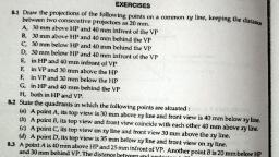
ORTHOGRAPHIC PROJECTIONS, OF POINTS, LINES, PLANES, AND SOLIDS., , TO DRAW PROJECTIONS OF ANY OBJECT,, ONE MUST HAVE FOLLOWING INFORMATION, A) OBJECT, { WITH IT’S DESCRIPTION, WELL DEFINED.}, , B) OBSERVER, { ALWAYS OBSERVING PERPENDICULAR TO RESP. REF.PLANE}., , C) LOCATION OF OBJECT,, { MEANS IT’S POSITION WITH REFFERENCE TO H.P. & V.P.}, TERMS ‘ABOVE’ & ‘BELOW’ WITH RESPECTIVE TO H.P., AND TERMS ‘INFRONT’ & ‘BEHIND’ WITH RESPECTIVE TO V.P, FORM 4 QUADRANTS., OBJECTS CAN BE PLACED IN ANY ONE OF THESE 4 QUADRANTS., IT IS INTERESTING TO LEARN THE EFFECT ON THE POSITIONS OF VIEWS ( FV, TV ), OF THE OBJECT WITH RESP. TO X-Y LINE, WHEN PLACED IN DIFFERENT QUADRANTS., STUDY ILLUSTRATIONS GIVEN ON HEXT PAGES AND NOTE THE RESULTS.TO MAKE IT EASY, HERE A POINT A IS TAKEN AS AN OBJECT. BECAUSE IT’S ALL VIEWS ARE JUST POINTS.
Page 41 :
NOTATIONS, FOLLOWING NOTATIONS SHOULD BE FOLLOWED WHILE NAMEING, DIFFERENT VIEWS IN ORTHOGRAPHIC PROJECTIONS., OBJECT, , POINT A, , LINE AB, , IT’S TOP VIEW, , a, , ab, , IT’S FRONT VIEW, , a’, , a’ b’, , IT’S SIDE VIEW, , a”, , a” b”, , SAME SYSTEM OF NOTATIONS SHOULD BE FOLLOWED, INCASE NUMBERS, LIKE 1, 2, 3 – ARE USED.
Page 42 :
VP, 2nd, , Quad., , 1ST Quad., , Y, , Observer, , HP, , X Y, X, , 3rd Quad., , 4th Quad., , THIS QUADRANT PATTERN,, IF OBSERVED ALONG X-Y LINE ( IN RED ARROW DIRECTION), WILL EXACTLY APPEAR AS SHOWN ON RIGHT SIDE AND HENCE,, IT IS FURTHER USED TO UNDERSTAND ILLUSTRATION PROPERLLY.
Page 43 :
POINT A IN, Point A is, ND, Placed In, 2 QUADRANT, different, A, quadrants, and it’s Fv & Tv, are brought in, same plane for, Observer to see, HP, clearly., Fv is visible as, it is a view on, VP. But as Tv is, is a view on Hp,, it is rotated, downward 900,, In clockwise, direction.The, In front part of, Hp comes below, xy line and the, part behind Vp, HP, comes above., Observe and, note the, process., , A, POINT A IN, RD, 3, QUADRANT, , POINT A IN, QUADRANT, , VP, a’, , VP, a’, , 1ST, A, , a, HP, , OBSERVER, , OBSERVER, , a, , a, HP, OBSERVER, , a’, , a, a’, , VP, , OBSERVER, , VP, , A, , POINT A IN, 4TH QUADRANT
Page 45 :
PROJECTIONS OF STRAIGHT LINES., INFORMATION REGARDING A LINE means, IT’S LENGTH,, POSITION OF IT’S ENDS WITH HP & VP, IT’S INCLINATIONS WITH HP & VP WILL BE GIVEN., AIM:- TO DRAW IT’S PROJECTIONS - MEANS FV & TV., SIMPLE CASES OF THE LINE, 1., , A VERTICAL LINE ( LINE PERPENDICULAR TO HP & // TO VP), , 2., , LINE PARALLEL TO BOTH HP & VP., , 3., , LINE INCLINED TO HP & PARALLEL TO VP., , 4., , LINE INCLINED TO VP & PARALLEL TO HP., , 5., , LINE INCLINED TO BOTH HP & VP., , STUDY ILLUSTRATIONS GIVEN ON NEXT PAGE, SHOWING CLEARLY THE NATURE OF FV & TV, OF LINES LISTED ABOVE AND NOTE RESULTS.
Page 46 :
For Tv, , (Pictorial Presentation), , Note:, Fv is a vertical line, Showing True Length, &, Tv is a point., , a’, , ., V.P, , 1., , A Line, perpendicular, to Hp, &, // to Vp, , A, FV, b’, , Y, Fo, rF, , B, , Orthographic Pattern, V.P., a’, , Fv, b’, , X, , Y, , v, , TV a b, , Tv a b, , X, , (Pictorial Presentation), 2., , ., V.P, , A Line, // to Hp, &, // to Vp, , ., F.V, , H.P., Orthographic Pattern, V.P., , Note:, Fv & Tv both are, // to xy, &, both show T. L., , For Tv, , b’, B, , a’, , Fv, , b’, , a’, A, , X, , Y, Fo, rF, , b, X, a, , Y, , v, , a, , V., T., , H.P., , Tv, , b
Page 47 :
., V.P, , 3., , b’, , a’, , b’, ., F.V, , B, , F., V., , A Line inclined to Hp, and, parallel to Vp, , V.P., , Fv inclined to xy, Tv parallel to xy., , q, , Y, , X, , q, , (Pictorial presentation), , A, , ., T.V, , X, , q, , a’, , Y, a, , b, , T.V., , b, , a, , H.P., Orthographic Projections, , 4., , A Line inclined to Vp, and, parallel to Hp, , ., V.P, , V.P., , Tv inclined to xy, Fv parallel to xy., , ., F.V b’, , a’, , Fv, , b’, , a’, A, , Ø, , B, , (Pictorial presentation), , X, , Y, a, , a, , Ø, , T.V., , Ø, , Tv, , b, , H.P., , b
Page 48 :
For Tv, , For Tv, 5., , b’, , a, , F.V, ., , Y, , a’, , For, Fv, A, , X, , a, , B, a, , Y, , a’, , On removal of object, i.e. Line AB, Fv as a image on Vp., Tv as a image on Hp,, , b, , For, Fv, A, , X, T.V., , b’, , ., V.P, , B, , F.V, ., , ., V.P, , A Line inclined to both, Hp and Vp, (Pictorial presentation), , b, , a, , b, T.V., , b, , V.P., b’, FV, a’, , a, , X, , Y, , Orthographic Projections, Fv is seen on Vp clearly., , To see Tv clearly, HP is, rotated 900 downwards,, , a, , Hence it comes below xy., , Note These Facts:Both Fv & Tv are inclined to xy., (No view is parallel to xy), Both Fv & Tv are reduced lengths., (No view shows True Length), , b, TV, , H.P., , b
Page 49 :
Note the procedure, When Fv & Tv known,, How to find True Length., (Views are rotated to determine, True Length & it’s inclinations, with Hp & Vp)., , Orthographic Projections, Means Fv & Tv of Line AB, are shown below,, with their apparent Inclinations, , a&b, , V.P., , V.P., , V.P., b’, , b’, , FV, a’, , a, , a’, Y, , Fv, , b, , q, , TL, , a’ q, , X, , Y, , a, , TV, , H.P., , b’ b1’, , b1 ’, , FV, , X, , a, , Note the procedure, When True Length is known,, How to locate Fv & Tv., (Component a-1 of TL is drawn, which is further rotated, to determine Fv), , b, , TV, , b2, , Here TV (ab) is not // to XY line, Hence it’s corresponding FV, a’ b’ is not showing, True Length &, True Inclination with Hp., , H.P., , Y, a, , 1, Ø, , b, Tv, , b, , In this sketch, TV is rotated, and made // to XY line., Hence it’s corresponding, FV a’ b1’ Is showing, True Length, &, True Inclination with Hp., , 1’, , X, , TV, , b, , a, , TL, , H.P., , TL, , b, , b1, , Here a -1 is component, of TL ab1 gives length of Fv., Hence it is brought Up to, Locus of a’ and further rotated, to get point b’. a’ b’ will be Fv., Similarly drawing component, of other TL(a’ b1‘) Tv can be drawn.
Page 50 :
The most important diagram showing graphical relations, among all important parameters of this topic., Study and memorize it as a CIRCUIT DIAGRAM, And use in solving various problems., , 1) True Length ( TL) – a’ b1’ & a b, 2) Angle of TL with Hp 3) Angle of TL with Vp –, 4) Angle of FV with xy –, 5) Angle of TV with xy –, , V.P., Distance between, End Projectors., , Ø, , a, b, , Important, TEN parameters, to be remembered, with Notations, used here onward, , 6) LTV (length of FV) – Component (a-1), , b1 ’, , b’, , q, , 7) LFV (length of TV) – Component (a’-1’), 8) Position of A- Distances of a & a’ from xy, , Fv, , a’, , q, , 9) Position of B- Distances of b & b’ from xy, , TL, , 10) Distance between End Projectors, , a, 1’, , LTV, , X, , Y, , LFV, , a, Ø, , 1, , NOTE this, , q& a, , Construct with a’, , Ø& b, , Construct with a, , b’ & b1’ on same locus., , b, , b & b1 on same locus., Tv, , H.P., , TL, , b, , b1, , Also Remember, True Length is never rotated. It’s horizontal component, is drawn & it is further rotated to locate view., Views are always rotated, made horizontal & further, extended to locate TL, q & Ø
Page 51 :
GROUP (A), PROBLEM 1), , GENERAL CASES OF THE LINE INCLINED TO BOTH HP & VP, ( based on 10 parameters)., , Line AB is 75 mm long and it is 300 &, 400 Inclined to Hp & Vp respectively., End A is 12mm above Hp and 10 mm, in front of Vp., Draw projections. Line is in 1st quadrant., , b’, FV, , SOLUTION STEPS:, 1) Draw xy line and one projector., 2) Locate a’ 12mm above xy line, & a 10mm below xy line., 3) Take 300 angle from a’ & 400 from, a and mark TL I.e. 75mm on both, lines. Name those points b1’ and b1, respectively., 4) Join both points with a’ and a resp., 5) Draw horizontal lines (Locus) from, both points., 6) Draw horizontal component of TL, a b1 from point b1 and name it 1., ( the length a-1 gives length of Fv, as we have seen already.), 7) Extend it up to locus of a’ and, rotating a’ as center locate b’ as, shown. Join a’ b’ as Fv., 8) From b’ drop a projector down, ward & get point b. Join a & b, I.e. Tv., , b’1, , TL, , q, a’, X, , Y, a, , LFV, , Ø, , TV, , 1, , TL, , b, , b1
Page 52 :
PROBLEM 2:, Line AB 75mm long makes 450 inclination with Vp while it’s Fv makes 550., End A is 10 mm above Hp and 15 mm in front of Vp.If line is in 1st quadrant, draw it’s projections and find it’s inclination with Hp., , b’1 LOCUS OF b, , b’, , TL, , 550, a’, , y, , X, 45 0, , LFV, , 1, , F, , a, , TL, , TV, , 1.Draw x-y line., 2.Draw one projector for a’ & a, 3.Locate a’ 10mm above x-y &, Tv a 15 mm below xy., 4.Draw a line 450 inclined to xy, from point a and cut TL 75 mm, on it and name that point b1, Draw locus from point b1, 5.Take 550 angle from a’ for Fv, above xy line., 6.Draw a vertical line from b1, up to locus of a and name it 1., It is horizontal component of, TL & is LFV., 7.Continue it to locus of a’ and, rotate upward up to the line, of Fv and name it b’.This a’ b’, line is Fv., 8. Drop a projector from b’ on, locus from point b1 and, name intersecting point b., Line a b is Tv of line AB., 9.Draw locus from b’ and from, a’ with TL distance cut point b1‘, 10.Join a’ b1’ as TL and measure, it’s angle at a’., It will be true angle of line with HP., , FV, , Solution Steps:-, , LOCUS OF b, , b, , b1
Page 53 :
SOLUTION STEPS:, 1.Draw xy line and one projector., 2.Locate a’ 10 mm above xy and, a 15 mm below xy line., 3.Draw locus from these points., 4.Draw Fv 500 to xy from a’ and, mark b’ Cutting 55mm on it., 5.Similarly draw Tv 600 to xy, from a & drawing projector from b’, Locate point b and join a b., 6.Then rotating views as shown,, locate True Lengths ab1 & a’b1’, and their angles with Hp and Vp., , b’, , FV, , PROBLEM 3:, Fv of line AB is 500 inclined to xy and measures 55, mm long while it’s Tv is 600 inclined to xy line., If, end A is 10 mm above Hp and 15 mm in front of, Vp, draw it’s projections,find TL, inclinations of line, with Hp & Vp., , X, , a’, , q, , b’1, , TL, 500, , y, a, , F, , 600, , TL, , b, , b1
Page 54 :
TL, , q, , LTV, , a’, , 1’, , X, , Y, a, , LFV, , F, , 1, , TL, , TV, , SOLUTION STEPS:, 1.Draw xy line and one projector., 2.Locate a’ 10 mm above xy and, a 15 mm below xy line., 3.Draw locus from these points., 4.Cut 60mm distance on locus of a’, & mark 1’ on it as it is LTV., 5.Similarly Similarly cut 50mm on, locus of a and mark point 1 as it is LFV., 6.From 1’ draw a vertical line upward, and from a’ taking TL ( 75mm ) in, compass, mark b’1 point on it., Join a’ b’1 points., 7. Draw locus from b’1, 8. With same steps below get b1 point, and draw also locus from it., 9. Now rotating one of the components, I.e. a-1 locate b’ and join a’ with it, to get Fv., 10. Locate tv similarly and measure, Angles q & F, , FV, , PROBLEM 4 :Line AB is 75 mm long .It’s Fv and Tv measure 50 mm & 60 mm long respectively., End A is 10 mm above Hp and 15 mm in front of Vp. Draw projections of line AB, if end B is in first quadrant.Find angle with Hp and Vp., b’, b’1, , b, , b1
Page 55 :
PROBLEM 5 :-, , SOLUTION STEPS:, 1.Draw xy line and one projector., 2.Locate c’ on xy and, c 50mm below xy line., 3.Draw locus from these points., 4.Draw locus of d 15 mm below xy, 5.Cut 50mm & 75 mm distances on, locus of d from c and mark points, d & d1 as these are Tv and line CD, lengths resp.& join both with c., 6.From d1 draw a vertical line upward, up to xy I.e. up to locus of c’ and, draw an arc as shown., 7 Then draw one projector from d to, meet this arc in d’ point & join c’ d’, 8. Draw locus of d’ and cut 75 mm, on it from c’ as TL, 9.Measure Angles, q & F, , d’, , d’1, , X, , c’, , q, d1, , d, TL, , TV, , c, , LOCUS OF d’ & d’1, , TL, , FV, , T.V. of a 75 mm long Line CD, measures 50 mm., End C is in Hp and 50 mm in front of Vp., End D is 15 mm in front of Vp and it is above Hp., Draw projections of CD and find angles with Hp and Vp., , F, , Y, LOCUS OF d & d1
Page 56 :
GROUP (B), PROBLEMS INVOLVING TRACES OF THE LINE., , TRACES OF THE LINE:THESE ARE THE POINTS OF INTERSECTIONS OF A LINE ( OR IT’S EXTENSION ), WITH RESPECTIVE REFFERENCE PLANES., A LINE ITSELF OR IT’S EXTENSION, WHERE EVER TOUCHES H.P.,, THAT POINT IS CALLED TRACE OF THE LINE ON H.P.( IT IS CALLED H.T.), SIMILARLY, A LINE ITSELF OR IT’S EXTENSION, WHERE EVER TOUCHES V.P.,, THAT POINT IS CALLED TRACE OF THE LINE ON V.P.( IT IS CALLED V.T.), , V.T.:-, , It is a point on Vp., Hence it is called Fv of a point in Vp., Hence it’s Tv comes on XY line.( Here onward named as v, , H.T.:-, , ), , It is a point on Hp., Hence it is called Tv of a point in Hp., Hence it’s Fv comes on XY line.( Here onward named as ’h’ )
Page 57 :
b’, , 1., 2., 3., 4., , Begin with FV. Extend FV up to XY line., Name this point h’, ( as it is a Fv of a point in Hp), Draw one projector from h’., Now extend Tv to meet this projector., This point is HT, , FV, , STEPS TO LOCATE HT., (WHEN PROJECTIONS ARE GIVEN.), a’, v, , h’, , VT’, , HT, , x, , y, a, , TV, , STEPS TO LOCATE VT., (WHEN PROJECTIONS ARE GIVEN.), , Observe & note :-, , 1., 2., , 2. VT’ & v always on one projector., , 3., 4., , Begin with TV. Extend TV up to XY line., Name this point v, ( as it is a Tv of a point in Vp), Draw one projector from v., Now extend Fv to meet this projector., This point is VT, , 1. Points h’ & v always on x-y line., , b, , 3. HT & h’ always on one projector., 4. FV - h’- VT’ always co-linear., 5. TV - v - HT always co-linear., , These points are used to, solve next three problems.
Page 58 :
PROBLEM 6 :- Fv of line AB makes 450 angle with XY line and measures 60 mm., Line’s Tv makes 300 with XY line. End A is 15 mm above Hp and it’s VT is 10 mm, below Hp. Draw projections of line AB,determine inclinations with Hp & Vp and locate HT, VT., , b’, , a’, 15, SOLUTION STEPS:h’, Draw xy line, one projector and, 300, locate fv a’ 15 mm above xy., 10, HT, Take 450 angle from a’ and, VT’, marking 60 mm on it locate point b’., Draw locus of VT, 10 mm below xy, & extending Fv to this locus locate VT., as fv-h’-vt’ lie on one st.line., Draw projector from vt, locate v on xy., From v take 300 angle downward as, Tv and it’s inclination can begin with v., Draw projector from b’ and locate b I.e.Tv point., Now rotating views as usual TL and, it’s inclinations can be found., Name extension of Fv, touching xy as h’, and below it, on extension of Tv, locate HT., , x, , q, , b’1, , 450, , v, , y, a, , Æ, , b, , b1
Page 59 :
PROBLEM 7 :, One end of line AB is 10mm above Hp and other end is 100 mm in-front of Vp., It’s Fv is 450 inclined to xy while it’s HT & VT are 45mm and 30 mm below xy respectively., Draw projections and find TL with it’s inclinations with Hp & VP., b’, b’, 1, , TL, , FV, a’, 10, , X, , v, , q, , LOCUS OF b’ & b’1, , 450, , h’, , Y, , 30, 45, VT’, , HT, , 100, , F, TV, , SOLUTION STEPS:Draw xy line, one projector and, locate a’ 10 mm above xy., Draw locus 100 mm below xy for points b & b1, a, Draw loci for VT and HT, 30 mm & 45 mm, below xy respectively., Take 450 angle from a’ and extend that line backward, to locate h’ and VT, & Locate v on xy above VT., Locate HT below h’ as shown., Then join v – HT – and extend to get top view end b., Draw projector upward and locate b’ Make a b & a’b’ dark., Now as usual rotating views find TL and it’s inclinations., , TL, , b, , b1, , LOCUS OF b & b1
Page 60 :
PROBLEM 8 :- Projectors drawn from HT and VT of a line AB, are 80 mm apart and those drawn from it’s ends are 50 mm apart., End A is 10 mm above Hp, VT is 35 mm below Hp, while it’s HT is 45 mm in front of Vp. Draw projections,, locate traces and find TL of line & inclinations with Hp and Vp., VT, b’, , SOLUTION STEPS:1.Draw xy line and two projectors,, 80 mm apart and locate HT & VT ,, 35 mm below xy and 55 mm above xy, respectively on these projectors., 2.Locate h’ and v on xy as usual., 3.Now just like previous two problems,, Extending certain lines complete Fv & Tv, And as usual find TL and it’s inclinations., , FV, Locus of a’, 10, , a’, , X, , 55, , TL, , q, 50, b, , TV, , 35, , F, , HT, 80, , y, , v, , h’, , a, , b’1, , TL, , b1
Page 61 :
Instead of considering a & a’ as projections of first point,, if v & VT’ are considered as first point , then true inclinations of line with, Hp & Vp i.e. angles q & F can be constructed with points VT’ & V respectively., b’, , b1 ’, , FV, , TL, , a’, X, , v, , Y, , F, q, , Then from point v & HT, angles b & F can be drawn., &, From point VT’ & h’, angles a & q can be drawn., , VT’, , THIS CONCEPT IS USED TO SOLVE, NEXT THREE PROBLEMS., , a, , TV, , TL, , b, , b1
Page 62 :
PROBLEM 9 :Line AB 100 mm long is 300 and 450 inclined to Hp & Vp respectively., End A is 10 mm above Hp and it’s VT is 20 mm below Hp, .Draw projections of the line and it’s HT., , b1 ’, , b’, FV, 100, , Locus of a & a1’, , a’, , SOLUTION STEPS:10, v, h’, X, Draw xy, one projector, F(450), and locate on it VT and V., 20, Draw locus of a’ 10 mm above xy., q (300), Take 300 from VT and draw a line., VT’, Where it intersects with locus of a’, name it a1’ as it is TL of that part., HT, From a1’ cut 100 mm (TL) on it and locate point b1’, Now from v take 450 and draw a line downwards, a, & Mark on it distance VT-a1’ I.e.TL of extension & name it a1, Extend this line by 100 mm and mark point b1., Draw it’s component on locus of VT’, & further rotate to get other end of Fv i.e.b’, Join it with VT’ and mark intersection point, (with locus of a1’ ) and name it a’, Now as usual locate points a and b and h’ and HT., , mm, , a1 ’, Y, , a1, , 10, , TV, , 0m, m, , b, , b1
Page 63 :
PROBLEM 10 :A line AB is 75 mm long. It’s Fv & Tv make 450 and 600 inclinations with X-Y line resp, End A is 15 mm above Hp and VT is 20 mm below Xy line. Line is in first quadrant., Draw projections, find inclinations with Hp & Vp. Also locate HT., b’, , b1 ’, , FV, 75, , a’, , Locus of a & a1’, 15, , X, , v, , 20, , Y, , F, q, , 450, VT’, SOLUTION STEPS:Similar to the previous only change, is instead of line’s inclinations,, views inclinations are given., So first take those angles from VT & v, Properly, construct Fv & Tv of extension,, then determine it’s TL( V-a1), and on it’s extension mark TL of line, and proceed and complete it., , a1 ’, , h’, 600, , mm, , HT, a, , a1, , 75, , TV, , b, , mm, , b1
Page 64 :
PROBLEM 11 :- The projectors drawn from VT & end A of line AB are 40mm apart., End A is 15mm above Hp and 25 mm in front of Vp. VT of line is 20 mm below Hp., If line is 75mm long, draw it’s projections, find inclinations with HP & Vp, b’, , b1 ’, , FV, , a’, 15, , X, 25, , 20, , m, m, 5, 7, , a1 ’, , v, VT’, , Y, F, , q, , a, , Draw two projectors for VT & end A, Locate these points and then, , YES !, YOU CAN COMPLETE IT., , 40mm, , TV, b, , b1
Page 65 :
GROUP (C), CASES OF THE LINES IN A.V.P., A.I.P. & PROFILE PLANE., , b’, , a’, X, , Line AB is in AIP as shown in above figure no 1., It’s FV (a’b’) is shown projected on Vp.(Looking in arrow direction), Here one can clearly see that the, Inclination of AIP with HP = Inclination of FV with XY line, , A.I, .P., , a, , B, A, , a, , b, A, , A.V.P., B, , Line AB is in AVP as shown in above figure no 2.., It’s TV (a b) is shown projected on Hp.(Looking in arrow direction), Here one can clearly see that the, Inclination of AVP with VP = Inclination of TV with XY line, , a, , b, b
Page 66 :
LINE IN A PROFILE PLANE ( MEANS IN A PLANE PERPENDICULAR TO BOTH HP & VP), For T.V., ORTHOGRAPHIC PATTERN OF LINE IN PROFILE PLANE, , VP, a’, , PP, , VT, , a’, , A, FV, , b’, , F, , a”, LSV, , b’, X, B, a, , q, , b”, HT, , Y, , a, , For, F.V, ., , TV, , b, b, , HP, Results:1. TV & FV both are vertical, hence arrive on one single projector., 2. It’s Side View shows True Length ( TL), 3. Sum of it’s inclinations with HP & VP equals to 900 ( q + F = 900 ), 4. It’s HT & VT arrive on same projector and can be easily located, From Side View., , OBSERVE CAREFULLY ABOVE GIVEN ILLUSTRATION AND 2nd SOLVED PROBLEM.
Page 67 :
PROBLEM 12 :- Line AB 80 mm long, makes 300 angle with Hp, and lies in an Aux.Vertical Plane 450 inclined to Vp., End A is 15 mm above Hp and VT is 10 mm below X-y line., Draw projections, fine angle with Vp and Ht., , Locus of a’ & a1’, , 15, X, , a’, 450, , VT, , HT, , Y, , q, , F, , b1 ’, , a1 ’, , h’, , v, , 10, , b’ Locus of b’, , a, AVP 450 to VP, , Simply consider inclination of AVP, as inclination of TV of our line,, well then?, , You sure can complete it, as previous problems!, Go ahead!!, , Locus of b’, b, , b1
Page 68 :
PROBLEM 13 :- A line AB, 75mm long, has one end A in Vp. Other end B is 15 mm above Hp, and 50 mm in front of Vp.Draw the projections of the line when sum of it’s, Inclinations with HP & Vp is 900, means it is lying in a profile plane., Find true angles with ref.planes and it’s traces., , Front view, After drawing xy line and one projector, Locate top view of A I.e point a on xy as, It is in Vp,, b’, Locate Fv of B i.e.b’15 mm above xy as, a, X, it is above Hp.and Tv of B i.e. b, 50 mm, below xy asit is 50 mm in front of Vp, Draw side view structure of Vp and Hp, top view, and locate S.V. of point B i.e. b’’, From this point cut 75 mm distance on Vp and, b, Mark a’’ as A is in Vp. (This is also VT of line.), From this point draw locus to left & get a’, HT, Extend SV up to Hp. It will be HT. As it is a Tv, Rotate it and bring it on projector of b., Now as discussed earlier SV gives TL of line, and at the same time on extension up to Hp & Vp, gives inclinations with those panes., , (VT), , a”, F, , Side View, ( True Length ), , VP, , SOLUTION STEPS:-, , VT, a’, , q, HP, , b”, (HT), , Y
Page 69 :
APPLICATIONS OF PRINCIPLES OF PROJECTIONS OF LINES, IN SOLVING CASES OF DIFFERENT PRACTICAL SITUATIONS., , In these types of problems some situation in the field, or, some object will be described ., It’s relation with Ground ( HP ), And, a Wall or some vertical object ( VP ) will be given., Indirectly information regarding Fv & Tv of some line or lines,, inclined to both reference Planes will be given, and, you are supposed to draw it’s projections, and, further to determine it’s true Length and it’s inclinations with ground., , Here various problems along with, actual pictures of those situations are given, for you to understand those clearly., Now looking for views in given ARROW directions,, YOU are supposed to draw projections & find answers,, Off course you must visualize the situation properly., , CHECK YOUR ANSWERS, WITH THE SOLUTIONS, GIVEN IN THE END., , ALL THE BEST !!
Page 70 :
PROBLEM 14:-Two objects, a flower (A) and an orange (B) are within a rectangular compound wall,, whose P & Q are walls meeting at 900. Flower A is 1M & 5.5 M from walls P & Q respectively., Orange B is 4M & 1.5M from walls P & Q respectively. Drawing projection, find distance between them, If flower is 1.5 M and orange is 3.5 M above the ground. Consider suitable scale.., TV, , B, , Wall P, , A, , FV, , Wall Q
Page 71 :
PROBLEM 15 :- Two mangos on a tree A & B are 1.5 m and 3.00 m above ground, and those are 1.2 m & 1.5 m from a 0.3 m thick wall but on opposite sides of it., If the distance measured between them along the ground and parallel to wall is 2.6 m,, Then find real distance between them by drawing their projections., TV, , B, , A, , FV, , 0.3M THICK
Page 72 :
PROBLEM 16 :- oa, ob & oc are three lines, 25mm, 45mm and 65mm, long respectively.All equally inclined and the shortest, is vertical.This fig. is TV of three rods OA, OB and OC, whose ends A,B & C are on ground and end O is 100mm, above ground. Draw their projections and find length of, each along with their angles with ground., , TV, , O, , A, , 65 mm, , m, 25m, , C, , FV, 45 mm, B
Page 73 :
PROBLEM 17:- A pipe line from point A has a downward gradient 1:5 and it runs due East-South., Another Point B is 12 M from A and due East of A and in same level of A. Pipe line from B runs, 200 Due East of South and meets pipe line from A at point C., Draw projections and find length of pipe line from B and it’s inclination with ground., , 5, , N, , A, , Do, wn, wa, 1, rd G, rad, ien, t 1:, 5, 12 M, , B, , E, , C, , S
Page 74 :
PROBLEM 18: A person observes two objects, A & B, on the ground, from a tower, 15 M high,, At the angles of depression 300 & 450. Object A is is due North-West direction of observer and, object B is due West direction. Draw projections of situation and find distance of objects from, observer and from tower also., , O, 300, , N, , 450, , A, S, , B, W
Page 75 :
PROBLEM 19:-Guy ropes of two poles fixed at 4.5m and 7.5 m above ground,, are attached to a corner of a building 15 M high, make 300 and 450 inclinations, with ground respectively.The poles are 10 M apart. Determine by drawing their, projections,Length of each rope and distance of poles from building., TV, C, , 15 M, , A, , 300, 4.5 M, 450, , B, , FV, , 10 M, , 7.5M
Page 76 :
PROBLEM 20:- A tank of 4 M height is to be strengthened by four stay rods from each corner, by fixing their other ends to the flooring, at a point 1.2 M and 0.7 M from two adjacent walls respectively,, as shown. Determine graphically length and angle of each rod with flooring., TV, , 4M, , 1.2 M, 7, 0., M, , FV
Page 77 :
PROBLEM 21:- A horizontal wooden platform 2 M long and 1.5 M wide is supported by four chains, from it’s corners and chains are attached to a hook 5 M above the center of the platform., Draw projections of the objects and determine length of each chain along with it’s inclination with ground., TV, Hook, , H, , 5M, , D, , A, , C, , 2M, , M, 1.5, , FV, , B
Page 78 :
PROBLEM 22., A room is of size 6.5m L ,5m D,3.5m high., An electric bulb hangs 1m below the center of ceiling., A switch is placed in one of the corners of the room, 1.5m above the flooring., Draw the projections an determine real distance between the bulb and switch., Ceiling, , TV, Bulb, all, Side w, , Front wall, , H, , Switch, , L, , D, , Observ, e, , r
Page 79 :
PROBLEM 23:A PICTURE FRAME 2 M WIDE AND 1 M TALL IS RESTING ON HORIZONTAL WALL RAILING, MAKES 350 INCLINATION WITH WALL. IT IS ATTAACHED TO A HOOK IN THE WALL BY TWO STRINGS., THE HOOK IS 1.5 M ABOVE WALL RAILING. DETERMINE LENGTH OF EACH CHAIN AND TRUE ANGLE BETWEEN THEM, , TV, , 350, 1.5 M, , 1M, , FV, 2M, , Wall railing
Page 80 :
PROBLEM NO.24, T.V. of a 75 mm long Line CD, measures 50 mm., End C is 15 mm below Hp and 50 mm in front of Vp., End D is 15 mm in front of Vp and it is above Hp., Draw projections of CD and find angles with Hp and Vp., , SOME CASES OF THE LINE, IN DIFFERENT QUADRANTS., REMEMBER:, BELOW HP- Means- Fv below xy, BEHIND V p- Means- Tv above xy., , d’, , d’1, , LOCUS OF d’ & d’1, , FV, , TL, , X, , Y, c’, , d, , q, , d1, TL, , TV, , c, , F, , LOCUS OF d & d1
Page 81 :
PROBLEM NO.25, End A of line AB is in Hp and 25 mm behind Vp., End B in Vp.and 50mm above Hp., Distance between projectors is 70mm., Draw projections and find it’s inclinations with Ht, Vt., b’, , LOCUS OF b’ & b’1, , b’1, , FV, a, , X, , TL, , F, , TV, a’, , TL, , b, , q, , b1, , Y, , LOCUS OF b & b1, , 70
Page 82 :
PROBLEM NO.26, End A of a line AB is 25mm below Hp and 35mm behind Vp., Line is 300 inclined to Hp., There is a point P on AB contained by both HP & VP., Draw projections, find inclination with Vp and traces., , a, , F, , b’, , b’1, , FV, , 35, , TL, , p p’, , X, , LOCUS OF b’ & b’1, , y, , p’1, 25, , TV, , a’, , q=300, , TL, , b, , LOCUS OF b & b1, , b1
Page 83 :
PROBLEM NO.27, End A of a line AB is 25mm above Hp and end B is 55mm behind Vp., The distance between end projectors is 75mm., If both it’s HT & VT coincide on xy in a point,, 35mm from projector of A and within two projectors,, b, Draw projections, find TL and angles and HT, VT., , b1, , TV, , 55, , a’, , TL, , q, , 25, , X, , Y, , Vt, Ht, , FV, a, , TL, , F, 35, , b’, , 75, , b’1
Page 84 :
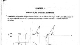
PROJECTIONS OF PLANES, In this topic various plane figures are the objects., , What is usually asked in the problem?, To draw their projections means F.V, T.V. & S.V., What will be given in the problem?, 1. Description of the plane figure., 2. It’s position with HP and VP., In which manner it’s position with HP & VP will be described?, 1.Inclination of it’s SURFACE with one of the reference planes will be given., 2. Inclination of one of it’s EDGES with other reference plane will be given, (Hence this will be a case of an object inclined to both reference Planes.), Study the illustration showing, surface & side inclination given on next page.
Page 85 :
CASE OF A RECTANGLE – OBSERVE AND NOTE ALL STEPS., SURFACE INCLINED TO HP, , SURFACE PARALLEL TO HP, , For Tv, , For T.V., , F or, , ORTHOGRAPHIC, TV-True Shape, FV- Line // to xy, , For, Fv, , F.V, ., , d’, c’, , VP, , d’, c’, , VP, , Fo, rF, .V., , ORTHOGRAPHIC, FV- Apparent Shape, TV-Previous Shape, , ORTHOGRAPHIC, FV- Inclined to XY, TV- Reduced Shape, , VP, , HP, , PICTORIAL PRESENTATION, For T.V., , PICTORIAL PRESENTATION, , PICTORIAL PRESENTATION, , a’, b’, , ONE SMALL SIDE INCLINED TO VP, , a 1’, , a’ ’, b, , d, , a1, , d1, , b, , c, , b1, , c1, , HP, , b1’, d1, , a, , A, , c 1’, , d1’, , c1, a1, , B, , HP, , b1, , C
Page 86 :
PROCEDURE OF SOLVING THE PROBLEM:, IN THREE STEPS EACH PROBLEM CAN BE SOLVED:( As Shown In Previous Illustration ), STEP 1. Assume suitable conditions & draw Fv & Tv of initial position., STEP 2. Now consider surface inclination & draw 2nd Fv & Tv., STEP 3. After this,consider side/edge inclination and draw 3rd ( final) Fv & Tv., ASSUMPTIONS FOR INITIAL POSITION:, (Initial Position means assuming surface // to HP or VP), 1.If in problem surface is inclined to HP – assume it // HP, Or If surface is inclined to VP – assume it // to VP, 2. Now if surface is assumed // to HP- It’s TV will show True Shape., And If surface is assumed // to VP – It’s FV will show True Shape., 3. Hence begin with drawing TV or FV as True Shape., 4. While drawing this True Shape –, keep one side/edge ( which is making inclination) perpendicular to xy line, ( similar to pair no. A on previous page illustration )., Now Complete STEP 2. By making surface inclined to the resp plane & project it’s other view., (Ref. 2nd pair, B on previous page illustration ), Now Complete STEP 3. By making side inclined to the resp plane & project it’s other view., (Ref. 3nd pair, C on previous page illustration ), , APPLY SAME STEPS TO SOLVE NEXT ELEVEN PROBLEMS
Page 87 :
Read problem and answer following questions, 1. Surface inclined to which plane? ------HP, 2. Assumption for initial position? ------// to HP, 3. So which view will show True shape? --- TV, 4. Which side will be vertical? ---One small side., Hence begin with TV, draw rectangle below X-Y, drawing one small side vertical., , Problem 1:, Rectangle 30mm and 50mm, sides is resting on HP on one, small side which is 300 inclined, to VP,while the surface of the, plane makes 450 inclination with, HP. Draw it’s projections., Surface // to Hp, , Surface inclined to Hp, , c’1, , d’c’, a’b’, , c’d’, a’ b’ 450, , X, d, , a1, , d1, , c, , b1, , c1, , 300, , a’1, , b1, , Y, Side, Inclined, to Vp, , d1, , b, , b’1, , a1, , a, , d’1, , c1
Page 88 :
Problem 2:, A 300 – 600 set square of longest side, 100 mm long, is in VP and 300 inclined, to HP while it’s surface is 450 inclined, to VP.Draw it’s projections, , Read problem and answer following questions, 1 .Surface inclined to which plane? ------VP, 2. Assumption for initial position? ------// to VP, 3. So which view will show True shape? --- FV, 4. Which side will be vertical? ------longest side., , (Surface & Side inclinations directly given), , a’, , Hence begin with FV, draw triangle above X-Y, keeping longest side vertical., , a’1, , c’, , side inclined to Hp, , c’1, , c’1, a’1, , b’, , X, , a, a, b, , b’1, , b’1, c, , 300, , b, , a1, , 450, , c, Surface // to Vp, , Surface inclined to Vp, , b1, c1, , Y
Page 89 :
Read problem and answer following questions, 1 .Surface inclined to which plane? ------VP, 2. Assumption for initial position? ------// to VP, 3. So which view will show True shape? --- FV, 4. Which side will be vertical? ------longest side., , Problem 3:, A 300 – 600 set square of longest side, 100 mm long is in VP and it’s surface, 450 inclined to VP. One end of longest, side is 10 mm and other end is 35 mm, above HP. Draw it’s projections, , Hence begin with FV, draw triangle above X-Y, keeping longest side vertical., , (Surface inclination directly given., Side inclination indirectly given), , a’, , First TWO steps are similar to previous problem., Note the manner in which side inclination is given., End A 35 mm above Hp & End B is 10 mm above Hp., So redraw 2nd Fv as final Fv placing these ends as said., , a’1, , c’, , c’1, , c’1, a’1, , 35, , X, , b’, , 10, , a, a, b, , b’1, , b’1, , c, , b, , a1, , 450, , c, , b1, c1, , Y
Page 90 :
Problem 4:, , Read problem and answer following questions, , A regular pentagon of 30 mm sides is, resting on HP on one of it’s sides with it’s, surface 450 inclined to HP., Draw it’s projections when the side in HP, makes 300 angle with VP, , 1. Surface inclined to which plane? ------HP, 2. Assumption for initial position? ------ // to HP, 3. So which view will show True shape? --- TV, 4. Which side will be vertical? -------- any side., Hence begin with TV,draw pentagon below, X-Y line, taking one side vertical., , SURFACE AND SIDE INCLINATIONS, ARE DIRECTLY GIVEN., , d’, , c’e’, X, , b’ a’, , c’e’, , d’, , 450, , a’1, e1, e1, , a1, , a, , b’1 Y, a1, , 300, , b1, , d1, , d, , d1, , b1, c, , c’1, , e’1, , b’ a’, , e, , b, , d’1, , c1, , c1
Page 91 :
Read problem and answer following questions, 1. Surface inclined to which plane? ------HP, 2. Assumption for initial position? ------ // to HP, 3. So which view will show True shape? --- TV, 4. Which side will be vertical? --------any side., Hence begin with TV,draw pentagon below, X-Y line, taking one side vertical., , Problem 5:, A regular pentagon of 30 mm sides is resting, on HP on one of it’s sides while it’s opposite, vertex (corner) is 30 mm above HP., Draw projections when side in HP is 300, inclined to VP., SURFACE INCLINATION INDIRECTLY GIVEN, SIDE INCLINATION DIRECTLY GIVEN:, , ONLY CHANGE is, the manner in which surface inclination is described:, One side on Hp & it’s opposite corner 30 mm above Hp., Hence redraw 1st Fv as a 2nd Fv making above arrangement., Keep a’b’ on xy & d’ 30 mm above xy., , X, , b’ a’, , c’e’, , c’e’, , 30, , 300, , a1, e1, , a1, , b1, , d1, , d, , d1, , b1, c, , b’1 Y, , a’1, e1, , a, , c’1, , e’1, , a’, b’, , d’, , e, , b, , d’1, , d’, , c1, , c1
Page 92 :
Problem 8: A circle of 50 mm diameter is, resting on Hp on end A of it’s diameter AC, which is 300 inclined to Hp while it’s Tv, is 450 inclined to Vp.Draw it’s projections., , a’, , c’, , b’ d’, , X, , d’1 Y, , 450, , d1, , a, , d1, , 1, , ca, , c1, , 1, , c1, , b, , Read problem and answer following questions, 1. Surface inclined to which plane? ------HP, 2. Assumption for initial position? ------ // to HP, 3. So which view will show True shape? --- TV, 4. Which diameter horizontal? ---------AC, Hence begin with TV,draw rhombus below, X-Y line, taking longer diagonal // to X-Y, , 1, , b, , b1, , The difference in these two problems is in step 3 only., In problem no.8 inclination of Tv of that AC is, given,It could be drawn directly as shown in 3rd step., While in no.9 angle of AC itself i.e. it’s TL, is, given. Hence here angle of TL is taken,locus of c1, Is drawn and then LTV I.e. a1 c1 is marked and, final TV was completed.Study illustration carefully., , a’, , b’ d’, d, , Note the difference in, construction of 3rd step, in both solutions., , c’1, , b’1, a’1, , 300, , d, a, , Problem 9: A circle of 50 mm diameter is, resting on Hp on end A of it’s diameter AC, which is 300 inclined to Hp while it makes, 450 inclined to Vp. Draw it’s projections., , a’, , c’, , d’, b’, , c’, , a’, , d’, b’, , d1, , c’, , d’1, d, , a’1, , a, , 300, , 1, , a, , ca, , 1, , TL, , c1, , 1, , b, , 1, , b, , c’1, , b’1, , b1, , c1
Page 93 :
Problem 10: End A of diameter AB of a circle is in HP, A nd end B is in VP.Diameter AB, 50 mm long is, 300 & 600 inclined to HP & VP respectively., Draw projections of circle., , Read problem and answer following questions, 1. Surface inclined to which plane? ------HP, 2. Assumption for initial position? ------ // to HP, 3. So which view will show True shape? --- TV, 4. Which diameter horizontal? ---------AB, Hence begin with TV,draw CIRCLE below, X-Y line, taking DIA. AB // to X-Y, , The problem is similar to previous problem of circle – no.9., But in the 3rd step there is one more change., Like 9th problem True Length inclination of dia.AB is definitely expected, but if you carefully note - the the SUM of it’s inclinations with HP & VP is 900., Means Line AB lies in a Profile Plane., Hence it’s both Tv & Fv must arrive on one single projector., So do the construction accordingly AND note, , X, , the case carefully.., , 300, , Y, 600, , TL, , SOLVE SEPARATELY, ON DRAWING SHEET, GIVING NAMES TO VARIOUS, POINTS AS USUAL,, AS THE CASE IS IMPORTANT
Page 94 :
Read problem and answer following questions, 1. Surface inclined to which plane? ------HP, 2. Assumption for initial position? ------ // to HP, 3. So which view will show True shape? --- TV, 4. Which diameter horizontal? ---------AC, Hence begin with TV,draw rhombus below, X-Y line, taking longer diagonal // to X-Y, , Problem 11:, A hexagonal lamina has its one side in HP and, Its apposite parallel side is 25mm above Hp and, In Vp. Draw it’s projections., Take side of hexagon 30 mm long., , ONLY CHANGE is the manner in which surface inclination, is described:, One side on Hp & it’s opposite side 25 mm above Hp., Hence redraw 1st Fv as a 2nd Fv making above arrangement., Keep a’b’ on xy & d’e’ 25 mm above xy., , 25, , X a’ b’, , c’ f’, , d’e’, , f, , a, , e, , b’, a’, , c’, , e’, d’, , f’, , e’1, , c1’, , f’1, a’1, e1, , f1, , a1, , e1, , d, c, , b1, , d1, c1, , b’1, d1, , f1, , Y, , c1, a1, , b, , d’1, , b1, , As 3rd step, redraw 2nd Tv keeping, side DE on xy line., Because it is in VP, as said in problem.
Page 95 :
FREELY SUSPENDED CASES., , IMPORTANT POINTS, , 1.In this case the plane of the figure always remains perpendicular to Hp., 2.It may remain parallel or inclined to Vp., 3.Hence TV in this case will be always a LINE view., 4.Assuming surface // to Vp, draw true shape in suspended position as FV., (Here keep line joining point of contact & centroid of fig. vertical ), 5.Always begin with FV as a True Shape but in a suspended position., AS shown in 1st FV., , Problem 12:, An isosceles triangle of 40 mm long, base side, 60 mm long altitude Is, freely suspended from one corner of, Base side.It’s plane is 450 inclined to, Vp. Draw it’s projections., , a’1, , a’, C, b’, , b’1, , g’, , g’1, , H, G, , c’1, , c’, X, , H/3, , A, , First draw a given triangle, With given dimensions,, Locate it’s centroid position, And, join it with point of suspension., , Y, , B, , b, , b, , a,g, , c, , a,, g, , 450, , c, , Similarly solve next problem, of Semi-circle
Page 96 :
IMPORTANT POINTS, Problem 13, :A semicircle of 100 mm diameter, is suspended from a point on its, straight edge 30 mm from the midpoint, of that edge so that the surface makes, an angle of 450 with VP., Draw its projections., , 1.In this case the plane of the figure always remains perpendicular to Hp., 2.It may remain parallel or inclined to Vp., 3.Hence TV in this case will be always a LINE view., 4.Assuming surface // to Vp, draw true shape in suspended position as FV., (Here keep line joining point of contact & centroid of fig. vertical ), 5.Always begin with FV as a True Shape but in a suspended position., AS shown in 1st FV., , A, , a’, , 20 mm, , p’, , P, b’, , G, , CG, , g’, c’, d’, , Y, , b, , 0.414R, , X, , c, a, , b c, , a p,g d, , e, , g, p,, d, , First draw a given semicircle, With given diameter,, Locate it’s centroid position, And, join it with point of suspension., , e’, , e
Page 97 :
To determine true shape of plane figure when it’s projections are given., BY USING AUXILIARY PLANE METHOD, WHAT WILL BE THE PROBLEM?, Description of final Fv & Tv will be given., You are supposed to determine true shape of that plane figure., Follow the below given steps:, 1., Draw the given Fv & Tv as per the given information in problem., 2., Then among all lines of Fv & Tv select a line showing True Length (T.L.), (It’s other view must be // to xy), 3., Draw x1-y1 perpendicular to this line showing T.L., 4., Project view on x1-y1 ( it must be a line view), 5., Draw x2-y2 // to this line view & project new view on it., , It will be the required answer i.e. True Shape., , The facts you must know:If you carefully study and observe the solutions of all previous problems,, You will find, IF ONE VIEW IS A LINE VIEW & THAT TOO PARALLEL TO XY LINE,, THEN AND THEN IT’S OTHER VIEW WILL SHOW TRUE SHAPE:, , NOW FINAL VIEWS ARE ALWAYS SOME SHAPE, NOT LINE VIEWS:, SO APPLYING ABOVE METHOD:, WE FIRST CONVERT ONE VIEW IN INCLINED LINE VIEW .(By using x1y1 aux.plane), THEN BY MAKING IT // TO X2-Y2 WE GET TRUE SHAPE., , Study Next, Four Cases
Page 98 :
Problem 14 Tv is a triangle abc. Ab is 50 mm long, angle cab is 300 and angle cba is 650., a’b’c’ is a Fv. a’ is 25 mm, b’ is 40 mm and c’ is 10 mm above Hp respectively. Draw projections, of that figure and find it’s true shape., , As per the procedure1.First draw Fv & Tv as per the data., 2.In Tv line ab is // to xy hence it’s other view a’b’ is TL. So draw x1y1 perpendicular to it., 3.Project view on x1y1., a) First draw projectors from a’b’ & c’ on x1y1., b) from xy take distances of a,b & c( Tv) mark on these projectors from x1y1. Name points a1b1 & c1., c) This line view is an Aux.Tv. Draw x2y2 // to this line view and project Aux. Fv on it., for that from x1y1 take distances of a’b’ & c’ and mark from x2y= on new projectors., 4.Name points a’1 b’1 & c’1 and join them. This will be the required true shape., Y1, a1b1, Y, 2, , 15, , b’, , TL, , a’, , 900, , b’1, , 15, 10, , C1, C’, X, , c, , a, , Y, , 50 mm, , a’1, , X2, c’1, , 650, , 300, , X1, , b, , TRUE SHAPE, ALWAYS FOR NEW FV TAKE, DISTANCES OF PREVIOUS FV, AND FOR NEW TV, DISTANCES, OF PREVIOUS TV, , REMEMBER!!
Page 99 :
Problem 15: Fv & Tv of a triangular plate are shown., Determine it’s true shape., 50, , USE SAME PROCEDURE STEPS, OF PREVIOUS PROBLEM:, , 25, , BUT THERE IS ONE DIFFICULTY:, , 15, a’, , NO LINE IS // TO XY IN ANY VIEW., MEANS NO TL IS AVAILABLE., IN SUCH CASES DRAW ONE LINE, // TO XY IN ANY VIEW & IT’S OTHER, VIEW CAN BE CONSIDERED AS TL, FOR THE PURPOSE., HERE a’ 1’ line in Fv is drawn // to xy., HENCE it’s Tv a-1 becomes TL., , c’, 1’, , 20, 10, , 15, , b’, X, , Y, a, , c, , TL, 40, , THEN FOLLOW SAME STEPS AND, DETERMINE TRUE SHAPE., (STUDY THE ILLUSTRATION), , x1, , 90 0, , 1, , a’1, , b, y1, , c’1, , y2, c1, , b’1, x2, , ALWAYS FOR NEW FV TAKE, DISTANCES OF PREVIOUS FV, AND FOR NEW TV, DISTANCES, OF PREVIOUS TV, , REMEMBER!!, , b1, , TRUE, , S HA P, , d1, , E
Page 100 :
PROBLEM 16: Fv & Tv both are circles of 50 mm diameter. Determine true shape of an elliptical plate., ADOPT SAME PROCEDURE., a c is considered as line // to xy., Then a’c’ becomes TL for the purpose., Using steps properly true shape can be, Easily determined., , 50D, , y1, , b’, , b1, , Study the illustration., TL, , a’, , y2, , ac1 1, , c’, , b’1, c’1, , d’, X, , X2, a’1, , ALWAYS, FOR NEW FV, TAKE DISTANCES OF, PREVIOUS FV AND, FOR NEW TV, DISTANCES, OF PREVIOUS TV, , REMEMBER!!, , d, , d, X1 1, Y, , a, , 50 D., , c, , b, , d’1, TRUE SHAPE
Page 101 :
Problem 17 : Draw a regular pentagon of, 30 mm sides with one side 300 inclined to xy., This figure is Tv of some plane whose Fv is, A line 450 inclined to xy., Determine it’s true shape., , b1, , TR, U, , E, , a1, , a’, , e1, , d1, , b’, e’, Y1, , c’, , d’, , 450, , X, , 300, , e, , REMEMBER!!, , E, , X1, , BUT ACTUALLY WE DONOT REQUIRE, TL TO FIND IT’S TRUE SHAPE, AS ONE, VIEW (FV) IS ALREADY A LINE VIEW., SO JUST BY DRAWING X1Y1 // TO THIS, VIEW WE CAN PROJECT VIEW ON IT, AND GET TRUE SHAPE:, , ALWAYS FOR NEW FV, TAKE DISTANCES OF, PREVIOUS FV AND FOR, NEW TV, DISTANCES OF, PREVIOUS TV, , AP, , c1, , IN THIS CASE ALSO TRUE LENGTH, IS NOT AVAILABLE IN ANY VIEW., , STUDY THE ILLUSTRATION.., , SH, , d, , a, , b, , c, , Y
Page 102 :
SOLIDS, , To understand and remember various solids in this subject properly,, those are classified & arranged in to two major groups., , Group A, , Group B, , Solids having top and base of same shape, , Solids having base of some shape, and just a point as a top, called apex., , Cylinder, , Cone, Prisms, , Triangular, , Cube, , Square, , ( A solid having, six square faces), , Pentagonal Hexagonal, , Pyramids, , Triangular, , Square, , Tetrahedron, ( A solid having, Four triangular faces), , Pentagonal Hexagonal
Page 103 :
SOLIDS, Dimensional parameters of different solids., Square Prism, , Corner of, base, , Cylinder, , Slant, Edge, Base, , Edge, of, Base, , Base, Edge, of, Base, , Cone, Apex, , Apex, , Top, Rectangular, Face, Longer, Edge, , Square Pyramid, , Triangular, Base, Face, , Corner of, base, , Sections of solids( top & base not parallel), , Base, , Generators, Imaginary lines, generating curved surface, of cylinder & cone., , Frustum of cone & pyramids., ( top & base parallel to each other)
Page 104 :
STANDING ON H.P, On it’s base., (Axis perpendicular to Hp, And // to Vp.), , F.V., , X, , X, , RESTING ON H.P, On one point of base circle., (Axis inclined to Hp, And // to Vp), , LYING ON H.P, On one generator., (Axis inclined to Hp, And // to Vp), , F.V., , F.V., , While observing Fv, x-y line represents Horizontal Plane. (Hp), , While observing Tv, x-y line represents Vertical Plane. (Vp), , T.V., , T.V., , STANDING ON V.P, On it’s base., Axis perpendicular to Vp, And // to Hp, , T.V., RESTING ON V.P, On one point of base circle., Axis inclined to Vp, And // to Hp, , LYING ON V.P, On one generator., Axis inclined to Vp, And // to Hp, , Y, , Y
Page 105 :
STEPS TO SOLVE PROBLEMS IN SOLIDS, Problem is solved in three steps:, STEP 1: ASSUME SOLID STANDING ON THE PLANE WITH WHICH IT IS MAKING INCLINATION., ( IF IT IS INCLINED TO HP, ASSUME IT STANDING ON HP), ( IF IT IS INCLINED TO VP, ASSUME IT STANDING ON VP), IF STANDING ON HP - IT’S TV WILL BE TRUE SHAPE OF IT’S BASE OR TOP:, IF STANDING ON VP - IT’S FV WILL BE TRUE SHAPE OF IT’S BASE OR TOP., BEGIN WITH THIS VIEW:, IT’S OTHER VIEW WILL BE A RECTANGLE ( IF SOLID IS CYLINDER OR ONE OF THE PRISMS):, IT’S OTHER VIEW WILL BE A TRIANGLE ( IF SOLID IS CONE OR ONE OF THE PYRAMIDS):, DRAW FV & TV OF THAT SOLID IN STANDING POSITION:, STEP 2: CONSIDERING SOLID’S INCLINATION ( AXIS POSITION ) DRAW IT’S FV & TV., STEP 3: IN LAST STEP, CONSIDERING REMAINING INCLINATION, DRAW IT’S FINAL FV & TV., GENERAL PATTERN ( THREE STEPS ) OF SOLUTION:, GROUP B SOLID., CONE, AXIS, AXIS, VERTICAL INCLINED HP, , AXIS, INCLINED VP, , Three steps, If solid is inclined to Hp, , AXIS, INCLINED HP, , AXIS, AXIS, VERTICAL INCLINED HP, , AXIS, INCLINED VP, , Three steps, If solid is inclined to Hp, , GROUP A SOLID., CYLINDER, , GROUP B SOLID., CONE, , GROUP A SOLID., CYLINDER, , AXIS, , er, , TO VP, , AXIS, INCLINED, VP, , Three steps, If solid is inclined to Vp, , AXIS, INCLINED HP, , AXIS, , er, , TO VP, , AXIS, INCLINED, VP, , Three steps, If solid is inclined to Vp, , Study Next Twelve Problems and Practice them separately !!
Page 106 :
CATEGORIES OF ILLUSTRATED PROBLEMS!, PROBLEM NO.1, 2, 3, 4, , GENERAL CASES OF SOLIDS INCLINED TO HP & VP, , PROBLEM NO. 5 & 6, , CASES OF CUBE & TETRAHEDRON, , PROBLEM NO. 7, , CASE, , OF FREELY SUSPENDED SOLID WITH SIDE VIEW., , PROBLEM NO. 8, , CASE, , OF CUBE ( WITH SIDE VIEW), , PROBLEM NO. 9, , CASE, , OF TRUE LENGTH INCLINATION WITH HP & VP., , PROBLEM NO. 10 & 11, , CASES OF COMPOSITE SOLIDS. (AUXILIARY PLANE), , PROBLEM NO. 12, , CASE, , OF A FRUSTUM (AUXILIARY PLANE)
Page 107 :
Problem 1. A square pyramid, 40, mm base sides and axis 60 mm long,, has a triangular face on the ground, and the vertical plane containing the, axis makes an angle of 450 with the, VP. Draw its projections. Take apex, nearer to VP, , Solution Steps :, Triangular face on Hp , means it is lying on Hp:, 1.Assume it standing on Hp., 2.It’s Tv will show True Shape of base( square), 3.Draw square of 40mm sides with one side vertical Tv &, taking 50 mm axis project Fv. ( a triangle), 4.Name all points as shown in illustration., 5.Draw 2nd Fv in lying position I.e.o’c’d’ face on xy. And project it’s Tv., 6.Make visible lines dark and hidden dotted, as per the procedure., 7.Then construct remaining inclination with Vp, ( Vp containing axis ic the center line of 2nd Tv.Make it 450 to xy as, shown take apex near to xy, as it is nearer to Vp) & project final Fv., , o’, a’b’, , c’d’, , o, , d1, , a1, , c, , For dark and dotted lines, , c1, , b1, , d1, , o1, , a1, o1, , Y, , o’1, , c’1, , d’1, , d1, , a1, , b, , d, , o’, , a, , c’d’, , X a’b’, , b’1, , a’1, , c1, , b 1 (APEX, c1, , 1.Draw proper outline of new view DARK. 2. Decide direction of an observer., 3. Select nearest point to observer and draw all lines starting from it-dark., 4. Select farthest point to observer and draw all lines (remaining)from it- dotted., , NEARER, TO V.P)., , b, , 1, (APEX, AWAY, FROM V.P.), , o1
Page 108 :
Solution Steps:, Resting on Hp on one generator, means lying on Hp:, 1.Assume it standing on Hp., 2.It’s Tv will show True Shape of base( circle ), 3.Draw 40mm dia. Circle as Tv &, taking 50 mm axis project Fv. ( a triangle), 4.Name all points as shown in illustration., 5.Draw 2nd Fv in lying position I.e.o’e’ on xy. And, project it’s Tv below xy., 6.Make visible lines dark and hidden dotted,, as per the procedure., 7.Then construct remaining inclination with Vp, ( generator o1e1 300 to xy as shown) & project final Fv., , Problem 2:, A cone 40 mm diameter and 50 mm axis, is resting on one generator on Hp, which makes 300 inclination with Vp, Draw it’s projections., For dark and dotted lines, 1.Draw proper outline of new vie, DARK., 2. Decide direction of an observer., 3. Select nearest point to observer, and draw all lines starting from, it-dark., 4. Select farthest point to observer, and draw all lines (remaining), from it- dotted., , a’, h’b, ’, c, ’g’, , h’1, , a’ h’b’, , c’ g, ’, g, , h, , f’ d’ e’, , o’, g1, , f, , f1, , g1, , h1, , e e1, b, , d, c, , a1, b1, , d1, c1, , b’1, , f’1, c’1, d’, 1, e’1, , o1, , a1, b1, , e1, d1, , Y, , o1, , 30, , o1, , h1, , f1, a, , a’1, , g’1, , d, ’, f, ’, e’, , X, , o’, , c1
Page 109 :
Problem 3:, A cylinder 40 mm diameter and 50 mm, axis is resting on one point of a base, circle on Vp while it’s axis makes 450, with Vp and Fv of the axis 350 with Hp., Draw projections.., , Solution Steps:, Resting on Vp on one point of base, means inclined to Vp:, 1.Assume it standing on Vp, 2.It’s Fv will show True Shape of base & top( circle ), 3.Draw 40mm dia. Circle as Fv & taking 50 mm axis project Tv., ( a Rectangle), 4.Name all points as shown in illustration., 5.Draw 2nd Tv making axis 450 to xy And project it’s Fv above xy., 6.Make visible lines dark and hidden dotted, as per the procedure., 7.Then construct remaining inclination with Hp, ( Fv of axis I.e. center line of view to xy as shown) & project final Tv., , 4’, 4’d’, , d’, 3’, c’ a’, , 1’ a’, , 4’, c’, , d’, , 3’, c’, , 3’, , 1’, , 1’, , a’, 2’ b’, c, , 350, , c, , bd, , 2’, , 450, , d1, , bd, , a, , b’, , Y, , b’, c1, b1, , a1, , 3, , 3, , a, 1, , 24, , 24, , 4, 3, , 1, , X, , 2’, , 1, , 2
Page 110 :
Solution Steps :, , 1.Assume it standing on Hp but as said on apex.( inverted )., 2.It’s Tv will show True Shape of base( square), 3.Draw a corner case square of 30 mm sides as Tv(as shown), Showing all slant edges dotted, as those will not be visible from top., 4.taking 50 mm axis project Fv. ( a triangle), 5.Name all points as shown in illustration., 6.Draw 2nd Fv keeping o’a’ slant edge vertical & project it’s Tv, 7.Make visible lines dark and hidden dotted, as per the procedure., 8.Then redrew 2nd Tv as final Tv keeping a1o1d1 triangular face, perpendicular to Vp I.e.xy. Then as usual project final Fv., , Problem 4:A square pyramid 30 mm base side, and 50 mm long axis is resting on it’s apex on Hp,, such that it’s one slant edge is vertical and a, triangular face through it is perpendicular to Vp., Draw it’s projections., , a’, , b’d’, , X, , c’, , a’, , o’, , bo, , ’, , o’, , d, a, , b’d, , c ao1, 1, , c’, , a’1, d’1, , b’1, c’1, , o’1, d1, b1, , Y, d1, , c1, , c1, a1 1, o, , b1
Page 111 :
Solution Steps:, , Problem 5: A cube of 50 mm long, edges is so placed on Hp on one, corner that a body diagonal is, parallel to Hp and perpendicular to, Vp Draw it’s projections., , 1.Assuming standing on Hp, begin with Tv,a square with all sides, equally inclined to xy.Project Fv and name all points of FV & TV., 2.Draw a body-diagonal joining c’ with 3’( This can become // to xy), 3.From 1’ drop a perpendicular on this and name it p’, 4.Draw 2nd Fv in which 1’-p’ line is vertical means c’-3’ diagonal, must be horizontal. .Now as usual project Tv.., 6.In final Tv draw same diagonal is perpendicular to Vp as said in problem., Then as usual project final FV., , a’, , a’1, , b’d, , d’1, , ’, , c’, p’, , c’1, 1’, , 3’, , 1’, , d, , d1, , d1, a, , c, , a1, , c1, , a1, , X, , c’, , p’, , 3’, , b, , b1, , 1’, , Y, b1, , b’d’, , c1, , a’, , d’1
Page 112 :
Solution Steps, As it is resting assume it standing on Hp., Begin with Tv , an equilateral triangle as side case as shown:, First project base points of Fv on xy, name those & axis line., From a’ with TL of edge, 50 mm, cut on axis line & mark o’, (as axis is not known, o’ is finalized by slant edge length), Then complete Fv., In 2nd Fv make face o’b’c’ vertical as said in problem., And like all previous problems solve completely., , Problem 6:A tetrahedron of 50 mm, long edges is resting on one edge on, Hp while one triangular face containing, this edge is vertical and 450 inclined to, Vp. Draw projections., , IMPORTANT:, Tetrahedron is a, special type, of triangular, pyramid in which, base sides &, slant edges are, equal in length., Solid of four faces., Like cube it is also, described by One X, dimension only.., Axis length, generally not given., , o’1, , o’, , o’, TL, , a’, , a’, , a, , 900, , b’, c’, , b’ c’, , c, , c1, , o, , a’1, b’1, , c’1, , 450, , a1, , c1, o1, , o1, , b1, , b, , b1, , a1, , Y
Page 113 :
FREELY SUSPENDED SOLIDS:, Positions of CG, on axis, from base, for different solids are shown below., , CG, , H/2, , H, CG, , H/4, GROUP A SOLIDS, ( Cylinder & Prisms), , GROUP B SOLIDS, ( Cone & Pyramids)
Page 114 :
Problem 7: A pentagonal pyramid, 30 mm base sides & 60 mm long axis,, is freely suspended from one corner of, base so that a plane containing it’s axis, remains parallel to Vp., Draw it’s three views., , Solution Steps:, In all suspended cases axis shows inclination with Hp., 1.Hence assuming it standing on Hp, drew Tv - a regular pentagon,corner case., 2.Project Fv & locate CG position on axis – ( ¼ H from base.) and name g’ and, Join it with corner d’, 3.As 2nd Fv, redraw first keeping line g’d’ vertical., 4.As usual project corresponding Tv and then Side View looking from., , LINE, , o’, , d’g’ VERTICAL, d’, , d”, c’e’, , FOR SIDE VIEW, , g’, , H, , e”, a’b’, , g’, , IMPORTANT:, When a solid is freely, suspended from a, corner, then line, joining point of, contact & C.G., remains vertical., ( Here axis shows, inclination with Hp.), So in all such cases,, assume solid standing, on Hp initially.), , X, , H/4, , c’ e’, , a’ b’, , e1, , e, , a1, d o1, , o, , d1, , b, , b1, c, , a”, , b”, o”, , d’, , a, , c”, , c1, , Y
Page 115 :
Solution Steps:, 1.Assuming it standing on Hp begin with Tv, a square of corner case., 2.Project corresponding Fv.& name all points as usual in both views., 3.Join a’1’ as body diagonal and draw 2nd Fv making it vertical (I’ on xy), 4.Project it’s Tv drawing dark and dotted lines as per the procedure., 5.With standard method construct Left-hand side view., , c’, , d’’, , c’, , X, d, , a, , b, , 1’, , 1’, , d1, , c, , b’’, , ’, , b’d’, , a’’, , b’d, , a’, , A cube of 50 mm long edges is so placed, on Hp on one corner that a body diagonal, through this corner is perpendicular to Hp, and parallel to Vp Draw it’s three views., , a’, , ( Draw a 450 inclined Line in Tv region ( below xy)., Project horizontally all points of Tv on this line and, reflect vertically upward, above xy.After this, draw, horizontal lines, from all points of Fv, to meet these, lines. Name points of intersections and join properly., For dark & dotted lines, locate observer on left side of Fv as shown.), , Problem 8:, , a1, , 1’, , c1, , b, , c’’, , Y
Page 116 :
Problem 9: A right circular cone,, 40 mm base diameter and 60 mm, long axis is resting on Hp on one, point of base circle such that it’s, axis makes 450 inclination with, Hp and 400 inclination with Vp., Draw it’s projections., , This case resembles to problem no.7 & 9 from projections of planes topic., In previous all cases 2nd inclination was done by a parameter not showing TL.Like, Tv of axis is inclined to Vp etc. But here it is clearly said that the axis is 400 inclined, to Vp. Means here TL inclination is expected. So the same construction done in those, Problems is done here also. See carefully the final Tv and inclination taken there., So assuming it standing on HP begin as usual., , o’, , o’, , o’1, a’1, , a’, , h’1, , ’g’, ’c, h’b, , f’ d’ e’, , 450, , g, h, , g1, h1, , f, , a, , e, b, , d, c, , a1, , c’1, , f’1, , ’, ’ e, , c’ g’, , g’1, d’f, , X, , a’ h’b’, , b’1, , o1, , d’1, 400, , e’1, , y, , Axis True Length, , f1, 1, , b1, , e1, , d1, , Axis Tv Length, , e1, , o1, , f1, , d1, , g1, , c1, Axis Tv Length, , c1, b1, , 1, h1, , a1, , Locus of, Center 1
Page 117 :
Y, , 1, , X, , (A, VP, 4, , 50, to, , Vp, ), , 450, , T.V., , 1, , Aux.F.V., , X, , Steps :, Draw Fv of lying prism, ( an equilateral Triangle), And Fv of a leaning pyramid., Project Tv of both solids., Draw x1y1 450 inclined to xy, and project aux.Fv on it., Mark the distances of first FV, from first xy for the distances, of aux. Fv from x1y1 line., Note the observer’s directions, Shown by arrows and further, steps carefully., , F.V., , y, , Problem 10: A triangular prism,, 40 mm base side 60 mm axis, is lying on Hp on one rectangular face, with axis perpendicular to Vp., One square pyramid is leaning on it’s face, centrally with axis // to vp. It’s base side is, 30 mm & axis is 60 mm long resting on Hp, on one edge of base.Draw FV & TV of, both solids.Project another FV, on an AVP 450 inclined to VP.
Page 118 :
Problem 11:A hexagonal prism of, base side 30 mm longand axis 40 mm long,, is standing on Hp on it’s base with, one base edge // to Vp., A tetrahedron is placed centrally, on the top of it.The base of tetrahedron is, a triangle formed by joining alternate corners, of top of prism..Draw projections of both solids., Project an auxiliary Tv on AIP 450 inclined to Hp., , b’ f’, , d’, , c’ e’, , Y1, , 45 0, , a’, , to, H, , p), , TL, , Fv, , (A, IP, , STEPS:, Draw a regular hexagon as Tv of, standing prism With one side // to xy, and name the top points.Project it’s Fv –, a rectangle and name it’s top., Now join it’s alternate corners, a-c-e and the triangle formed is base, of a tetrahedron as said., Locate center of this triangle, & locate apex o, Extending it’s axis line upward, mark apex o’, By cutting TL of edge of tetrahedron, equal to a-c. and complete Fv, of tetrahedron., Draw an AIP ( x1y1) 450 inclined to xy, And project Aux.Tv on it by using similar, Steps like previous problem., , o’, , X, , Aux.Tv, , Y, e, , f, , Tva, , o, , o1, , e1, , 450, f1, d, , d1, a1, , c1, b1, , b, , c, X1
Page 119 :
Problem 12: A frustum of regular hexagonal pyramid is standing on it’s larger base, On Hp with one base side perpendicular to Vp.Draw it’s Fv & Tv., Project it’s Aux.Tv on an AIP parallel to one of the slant edges showing TL., Base side is 50 mm long , top side is 30 mm long and 50 mm is height of frustum., , Fv, 1’, , 2’5’, , AIP // to slant edge, Showing true length, i.e. a’- 1’, , Y1, , 3’4’, , 4, , TL, , 5, , 3, , 1, X, , a’, , Aux.Tv, , c’ d’ Y, , b’ e’, , e, , a, , d1, d, , Tv, , 5, , 4, , 2, , e1, X1, , 1, , b, , 2, , 3, , c, , a1, , c1, b1
Page 120 :
ENGINEERING APPLICATIONS, OF, THE PRINCIPLES, OF, PROJECTIONS OF SOLIDES., , 1. SECTIONS OF SOLIDS., 2. DEVELOPMENT., 3. INTERSECTIONS., STUDY CAREFULLY, THE ILLUSTRATIONS GIVEN ON, NEXT SIX PAGES !
Page 121 :
SECTIONING A SOLID., An object ( here a solid ) is cut by, some imaginary cutting plane, to understand internal details of that object., , The action of cutting is called, SECTIONING a solid, &, The plane of cutting is called, SECTION PLANE., , Two cutting actions means section planes are recommended., OBSERVER, , A) Section Plane perpendicular to Vp and inclined to Hp., ( This is a definition of an Aux. Inclined Plane i.e. A.I.P.), NOTE:- This section plane appears, as a straight line in FV., B) Section Plane perpendicular to Hp and inclined to Vp., ( This is a definition of an Aux. Vertical Plane i.e. A.V.P.), NOTE:- This section plane appears, as a straight line in TV., Remember:1. After launching a section plane, either in FV or TV, the part towards observer, is assumed to be removed., 2. As far as possible the smaller part is, assumed to be removed., , ASSUME, UPPER PART, REMOVED, , AN, PL ., N V, TO N F, C, I, SE, , E, , (A), , (B), , ASSUME, LOWER PART, REMOVED, OBSERVER, , SE, CT, ON, IN PLA, TV NE, .
Page 122 :
ILLUSTRATION SHOWING, IMPORTANT TERMS, IN SECTIONING., , For TV, , Fo, , rT, ru, eS, ha, pe, , SECTION, PLANE, TRUE SHAPE, Of SECTION, x, , y, , Apparent Shape, of section, SECTION LINES, (450 to XY), , SECTIONAL T.V.
Page 123 :
Section Plane, Ellipse, Section PlaneTriangle Through Generators, Through Apex, , Par, abo, la, , Typical Section Planes, &, Typical Shapes, Of, Sections., , Section Plane Parallel, to end generator., Ellipse, , Cylinder through, generators., , Section Plane Hyperbola, Parallel to Axis., Trapezium, , Sq. Pyramid through, all slant edges
Page 124 :
DEVELOPMENT OF SURFACES OF SOLIDS., MEANING:ASSUME OBJECT HOLLOW AND MADE-UP OF THIN SHEET. CUT OPEN IT FROM ONE SIDE AND, UNFOLD THE SHEET COMPLETELY. THEN THE SHAPE OF THAT UNFOLDED SHEET IS CALLED, DEVELOPMENT OF LATERLAL SUEFACES OF THAT OBJECT OR SOLID., LATERLAL SURFACE IS THE SURFACE EXCLUDING SOLID’S TOP & BASE., ENGINEERING APLICATION:, THERE ARE SO MANY PRODUCTS OR OBJECTS WHICH ARE DIFFICULT TO MANUFACTURE BY, CONVENTIONAL MANUFACTURING PROCESSES, BECAUSE OF THEIR SHAPES AND SIZES., THOSE ARE FABRICATED IN SHEET METAL INDUSTRY BY USING, DEVELOPMENT TECHNIQUE. THERE IS A VAST RANGE OF SUCH OBJECTS., EXAMPLES:Boiler Shells & chimneys, Pressure Vessels, Shovels, Trays, Boxes & Cartons, Feeding Hoppers,, Large Pipe sections, Body & Parts of automotives, Ships, Aeroplanes and many more., , WHAT IS, OUR OBJECTIVE, IN THIS TOPIC ?, , But before going ahead,, note following, Important points., , To learn methods of development of surfaces of, different solids, their sections and frustums., 1. Development is different drawing than PROJECTIONS., 2. It is a shape showing AREA, means it’s a 2-D plain drawing., 3. Hence all dimensions of it must be TRUE dimensions., 4. As it is representing shape of an un-folded sheet, no edges can remain hidden, And hence DOTTED LINES are never shown on development., , Study illustrations given on next page carefully.
Page 125 :
Development of lateral surfaces of different solids., (Lateral surface is the surface excluding top & base), A Rectangle, , Cone: (Sector of circle), , Pyramids: (No.of triangles), , L, , L, , S, , Cylinder:, , H, , S, , pD, , D, , q, , H= Height D= base diameter, , Prisms:, , =, , L= Slant edge., S = Edge of base, , +, , R=Base circle radius., L=Slant height., R 3600, q, L, , No.of Rectangles, , H, , S, , S, , H= Height S = Edge of base, , Tetrahedron: Four Equilateral Triangles, , All sides, equal in length, , Cube: Six Squares.
Page 126 :
FRUSTUMS, DEVELOPMENT OF, FRUSTUM OF CONE, , DEVELOPMENT OF, FRUSTUM OF SQUARE PYRAMID, Base side, Top side, , L, , L, L1, , L1, , q, , =, , R 3600, L, , +, , q, , R= Base circle radius of cone, L= Slant height of cone, L1 = Slant height of cut part., , L= Slant edge of pyramid, L1 = Slant edge of cut part., , STUDY NEXT NINE PROBLEMS OF, SECTIONS & DEVELOPMENT
Page 127 :
Problem 1: A pentagonal prism , 30 mm base side & 50 mm axis, is standing on Hp on it’s base whose one side is perpendicular to Vp., It is cut by a section plane 450 inclined to Hp, through mid point of axis., Draw Fv, sec.Tv & sec. Side view. Also draw true shape of section and, Development of surface of remaining solid., UE, R, T, , SH, , C, , E, AP, , B, , D, , A, , Y1, , A, , E, c’, , X1, , b’, , d”, , d’, , e’, , a”, , X, e, , B, , C, , D, , E, , A, , c”, b”, , e”, , a’, , Solution Steps:for sectional views:, Draw three views of standing prism., Locate sec.plane in Fv as described., Project points where edges are getting, Cut on Tv & Sv as shown in illustration., Join those points in sequence and show, Section lines in it., Make remaining part of solid dark., , Y, , DEVELOPMENT, , d, , For True Shape:, a, Draw x1y1 // to sec. plane, Draw projectors on it from, cut points., Mark distances of points, of Sectioned part from Tv,, on above projectors from, x1y1 and join in sequence., Draw section lines in it., It is required true shape., , c, b, , For Development:, Draw development of entire solid. Name from, cut-open edge I.e. A. in sequence as shown., Mark the cut points on respective edges., Join them in sequence in st. lines., Make existing parts dev.dark.
Page 128 :
Problem 2: A cone, 50 mm base diameter and 70 mm axis is, standing on it’s base on Hp. It cut by a section plane 450 inclined, to Hp through base end of end generator.Draw projections,, sectional views, true shape of section and development of surfaces, of remaining solid., , OF, , ON, , Y1, , A, , SECTIONAL S.V, o’, , SE, PL CT, AN IO, E N, , UE, R, T, , PE, A, SH, , TI, C, SE, , Solution Steps:for sectional views:, Draw three views of standing cone., Locate sec.plane in Fv as described., Project points where generators are, getting Cut on Tv & Sv as shown in, illustration.Join those points in, sequence and show Section lines in it., Make remaining part of solid dark., B, DEVELOPMENT, , C, D, , X1, , E, X, , a’ h’b’, , c’ g’, , f’ d’, , e’, , g, For True Shape:, Draw x1y1 // to sec. plane, Draw projectors on it from, cut points., Mark distances of points, of Sectioned part from Tv,, on above projectors from, x1y1 and join in sequence., Draw section lines in it., It is required true shape., , h, , g” h”f”, , a”e”, , b”d” c”, , Y, , F, G, , f, , a, , e, b, , d, c, , SECTIONAL T.V, , For Development:, Draw development of entire solid., Name from cut-open edge i.e. A., in sequence as shown.Mark the cut, points on respective edges., Join them in sequence in curvature., Make existing parts dev.dark., , H, A
Page 129 :
Problem 3: A cone 40mm diameter and 50 mm axis is resting on one generator on Hp( lying on Hp), which is // to Vp.. Draw it’s projections.It is cut by a horizontal section plane through it’s base, center. Draw sectional TV, development of the surface of the remaining part of cone., , Follow similar solution steps for Sec.views - True shape – Development as per previous problem!, DEVELOPMENT, A, , o’, a’, h’b, ’, c’g, ’, , B, , c’ g’, , f’ d’ e’, , g, h, , a, , o’ Y, , e’, , a’ h’b’, , f1, , d, c, , E, , h1, , e e1, , O, b, , O, , g1, f, , C, D, , d’f ’, , X, , HORIZONTAL, SECTION PLANE, , a1, , F, G, , o1, H, , b1, , d1, , A, , c1, SECTIONAL T.V, (SHOWING TRUE SHAPE OF SECTION)
Page 130 :
c’ f’, , a’ b’, , Problem 4: A hexagonal prism. 30 mm base side &, 55 mm axis is lying on Hp on it’s rect.face with axis, // to Vp. It is cut by a section plane normal to Hp and, 300 inclined to Vp bisecting axis., Draw sec. Views, true shape & development., , Note the steps to locate, Points 1, 2 , 5, 6 in sec.Fv:, Those are transferred to, 1st TV, then to 1st Fv and, Then on 2nd Fv., , d’ e’, , SECTIONAL F.V., 4, , Use similar steps for sec.views & true shape., , a’ b’, , 3, , 1, , 6, , NOTE: for development, always cut open object from, From an edge in the boundary of the view in which, sec.plane appears as a line., Here it is Tv and in boundary, there is c1 edge.Hence, it is opened from c and named C,D,E,F,A,B,C., , c’ f’, , 2, , 5, , 8, , f, 1,2, , e, , a, , 7, , f1, 3,8, , a1 e1, , 4,7, , d, , b, , Y, , d’ e’, , X, , A.V.P300 inclined to Vp, Through mid-point of axis., , b1 d1, 5,6, , c X1, 1, , AS SECTION PLANE IS IN T.V.,, CUT OPEN FROM BOUNDRY EDGE C1 FOR DEVELOPMENT., , c1, , 8, , C, , E, , F, , 7, , 2, , TR, UE, , D, , 6, , 3, , SH, A, , PE, O, , FS, EC, TI O, , 4, , Y1, , 5, , N, , DEVELOPMENT, , A, , B, , C
Page 131 :
E, AP, H, S, UE 2, R, T, , Problem 5:A solid composed of a half-cone and half- hexagonal pyramid is, shown in figure.It is cut by a section plane 450 inclined to Hp, passing through, mid-point of axis.Draw F.v., sectional T.v.,true shape of section and, development of remaining part of the solid., ( take radius of cone and each side of hexagon 30mm long and axis 70mm.), , 3, 4, Y1, , 5, 1, , O’, , Note:, , A, OP, ME, NT, , 6, , 4’, X1, , 2’ 6’, , 3’, 5’, , B, , DE, VE, L, , 7, , F.V., , 4, , C, 2, , 3, , d’e’, , c’f’, f, , a’, , Y, , O, , 5, , 4, , 4, , 1, , 5, , 6, , a, , F, , 3, 2, c, , E, , 7, , g, , SECTIONAL 7, TOP VIEW., , d, , g’b’, , 6, , e, , D, , 1, , 1’ 7’, X, , Fv & TV 8f two solids, sandwiched, Section lines style in both:, Development of, half cone & half pyramid:, , b, , G, A
Page 132 :
Problem 6: Draw a semicircle 0f 100 mm diameter and inscribe in it a largest, circle.If the semicircle is development of a cone and inscribed circle is some, curve on it, then draw the projections of cone showing that curve., , =, , 1’, 7’, , L, , c’ g’, , a’ h’ b’, , 3’ 5’, , 4’, , d’f’ e’ Y, , 5, , 7, , o, , f, , 4, , 1, , 3, 2, , c, , G, 6, H, , 1, , 6, , h, , b, , 5, , 3, , B, , g, , a, , F, , 4, , 2, 6’, 2’, , X, , E, , D, , +, , R=Base circle radius., L=Slant height., R 3600 C, q, L, , o’, , TO DRAW PRINCIPAL, VIEWS FROM GIVEN, DEVELOPMENT., , d, , e, , A, , q, O, , 7, A, L, , Solution Steps:, Draw semicircle of given diameter, divide it in 8 Parts and inscribe in it, a largest circle as shown.Name intersecting points 1, 2, 3 etc., Semicircle being dev.of a cone it’s radius is slant height of cone.( L ), Then using above formula find R of base of cone. Using this data, draw Fv & Tv of cone and form 8 generators and name., Take o -1 distance from dev.,mark on TL i.e.o’a’ on Fv & bring on o’b’, and name 1’ Similarly locate all points on Fv. Then project all on Tv, on respective generators and join by smooth curve.
Page 133 :
TO DRAW PRINCIPAL, VIEWS FROM GIVEN, DEVELOPMENT., , Problem 7:Draw a semicircle 0f 100 mm diameter and inscribe in it a largest, rhombus.If the semicircle is development of a cone and rhombus is some curve, on it, then draw the projections of cone showing that curve., , Solution Steps:, Similar to previous, Problem:, , o’, E, 4, , D, , 5, , 3, , C, , F, G, , 6, , 2, 2’ 6’, , X, , a’ h’ b’, , B, , 3’ 5’, , c’ g’, , f’ d’ e’, , 1’ 7’, , 4’, , g, 7, , f, , 5, , 4, , b, , 3, 1, , 2, , c, , d, , e, , O, , L, , R=Base circle radius., L=Slant height., R 3600, q, L, , =, , +, , a, , H, , q, , Y, A, , 6, , h, , 7, , 1, , A
Page 134 :
Problem 8: A half cone of 50 mm base diameter, 70 mm axis, is standing on it’s half base on HP with it’s flat face, parallel and nearer to VP.An inextensible string is wound round it’s surface from one point of base circle and, brought back to the same point.If the string is of shortest length, find it and show it on the projections of the cone., , TO DRAW A CURVE ON, PRINCIPAL VIEWS, FROM DEVELOPMENT., o’, A, B, C, , 1, 2’, , 3’, , 4’, , 1’, , D, , 2, 3, , X, , a’, , b’, , a, , b, , 1, , c’, , d’, , o, , 4, , e’, e, , Y, , E, , 4, O, , 3, 2, , d, , c, A, , Concept: A string wound, from a point up to the same, Point, of shortest length, Must appear st. line on it’s, Development., Solution steps:, Hence draw development,, Name it as usual and join, A to A This is shortest, Length of that string., Further steps are as usual., On dev. Name the points of, Intersections of this line with, Different generators.Bring, Those on Fv & Tv and join, by smooth curves., Draw 4’ a’ part of string dotted, As it is on back side of cone.
Page 135 :
Problem 9:, A particle which is initially on base circle of a cone, standing, on Hp, moves upwards and reaches apex in one complete turn around the cone., Draw it’s path on projections of cone as well as on it’s development., Take base circle diameter 50 mm and axis 70 mm long., , It’s a construction of curve, Helix of one turn on cone:, , o’, 7’, , DEVELOPMENT, , HELIX CURVE, , 6’, , A, , 5’, 4’, 3’, , B, 1, , 2’, , C, , 1’, , X, , 2, , Y, a’ h’b’, , c’ gg’, , f’ d’ e’, , h, , O, , f, 6, 7, , a, , O, , 5, , D, , 3, 7, , 4, 6, , E, , 5, , F, , e, , 4, , G, , 3, , b, , 1, , 2, , d, H, , c, A, , Draw Fv & Tv & dev.as usual, On all form generators & name., Construction of curve Helix::, Show 8 generators on both views, Divide axis also in same parts., Draw horizontal lines from those, points on both end generators., 1’ is a point where first horizontal, Line & gen. b’o’ intersect., 2’ is a point where second horiz., Line & gen. c’o’ intersect., In this way locate all points on Fv., Project all on Tv.Join in curvature., For Development:, Then taking each points true, Distance From resp.generator, from apex, Mark on development, & join.
Page 136 :
INTERPENETRATION OF SOLIDS, WHEN ONE SOLID PENETRATES ANOTHER SOLID THEN THEIR SURFACES INTERSECT, AND, AT THE JUNCTION OF INTERSECTION A TYPICAL CURVE IS FORMED,, WHICH REMAINS COMMON TO BOTH SOLIDS., THIS CURVE IS CALLED CURVE OF INTERSECTION, AND, IT IS A RESULT OF INTERPENETRATION OF SOLIDS., , PURPOSE OF DRAWING THESE CURVES:WHEN TWO OBJECTS ARE TO BE JOINED TOGATHER, MAXIMUM SURFACE CONTACT BETWEEN BOTH, BECOMES A BASIC REQUIREMENT FOR STRONGEST & LEAK-PROOF JOINT., , Curves of Intersections being common to both Intersecting solids,, show exact & maximum surface contact of both solids., , Study Following Illustrations Carefully., Minimum Surface Contact., ( Point Contact), , Square Pipes., , Circular Pipes., , (Maximum Surface Contact), Lines of Intersections., , Square Pipes., , Curves of Intersections., , Circular Pipes.
Page 137 :
SOME ACTUAL OBJECTS ARE SHOWN, SHOWING CURVES OF INTERSECTIONS., BY WHITE ARROWS., , A machine component having, two intersecting cylindrical, surfaces with the axis at, acute angle to each other., , A Feeding Hopper, In industry., , An Industrial Dust collector., Intersection of two cylinders., , Forged End of a, Connecting Rod., , Two Cylindrical, surfaces., , Intersection of a Cylindrical, main and Branch Pipe., , Pump lid having shape of a, hexagonal Prism and, Hemi-sphere intersecting, each other.
Page 138 :
FOLLOWING CASES ARE SOLVED., REFFER ILLUSTRATIONS, AND, NOTE THE COMMON, CONSTRUCTION, FOR ALL, 1.CYLINDER TO CYLINDER2., 2.SQ.PRISM TO CYLINDER, 3.CONE TO CYLINDER, 4.TRIANGULAR PRISM TO CYLNDER, 5.SQ.PRISM TO SQ.PRISM, 6.SQ.PRISM TO SQ.PRISM, ( SKEW POSITION), 7.SQARE PRISM TO CONE ( from top ), 8.CYLINDER TO CONE, , COMMON SOLUTION STEPS, One solid will be standing on HP, Other will penetrate horizontally., Draw three views of standing solid., Name views as per the illustrations., Beginning with side view draw three, Views of penetrating solids also., On it’s S.V. mark number of points, And name those(either letters or nos.), The points which are on standard, generators or edges of standing solid,, ( in S.V.) can be marked on respective, generators in Fv and Tv. And other, points from SV should be brought to, Tv first and then projecting upward, To Fv., Dark and dotted line’s decision should, be taken by observing side view from, it’s right side as shown by arrow., Accordingly those should be joined, by curvature or straight lines., Note:, Incase cone is penetrating solid Side view is not necessary., Similarly in case of penetration from top it is not required.
Page 139 :
Problem: A cylinder 50mm dia.and 70mm axis is completely penetrated, by another of 40 mm dia.and 70 mm axis horizontally Both axes intersect, & bisect each other. Draw projections showing curves of intersections., 2’ 4’, , 1’, , 3’, , 1”3”, , 4”, , a’, h”, , b”, , g”, , d’f’, , a’, X, , 2”, , a”, , b ’h’, c’g’, , CASE 1., CYLINDER STANDING, &, CYLINDER PENETRATING, , c”, d”, , f”, e”, , Y, 4, , 3, , 1, , 2
Page 140 :
Problem: A cylinder 50mm dia.and 70mm axis is completely penetrated, by a square prism of 25 mm sides.and 70 mm axis, horizontally. Both axes, Intersect & bisect each other. All faces of prism are equally inclined to Hp., Draw projections showing curves of intersections., 2’ 4’, , 1’, , 4”, , 3’, , a’, , a’, , b’, d’, , c’, , X, , 2”, , a”, d”, , b’, d’, , c’, , 1”3”, , CASE 2., CYLINDER STANDING, &, SQ.PRISM PENETRATING, , b”, , c”, Y, , 4, , 3, , 1, , 2
Page 141 :
CASE 3., CYLINDER STANDING, &, CONE PENETRATING, , Problem: A cylinder of 80 mm diameter and 100 mm axis, is completely penetrated by a cone of 80 mm diameter and, 120 mm long axis horizontally.Both axes intersect & bisect, each other. Draw projections showing curve of intersections., 7’, 6’ 8’, 1’ 5’, , 2’ 4’, 3’, , X, , Y, 1, 28, 37, , 46, 5
Page 142 :
Problem: A sq.prism 30 mm base sides.and 70mm axis is completely penetrated, CASE 4., by another square prism of 25 mm sides.and 70 mm axis, horizontally. Both axesSQ.PRISM STANDING, Intersects & bisect each other. All faces of prisms are equally inclined to Vp., &, Draw projections showing curves of intersections., SQ.PRISM PENETRATING, , 2’4’, , 1’, , 3’, , a’, , 4”, , a’, b’, d’, , 1”3”, , a”, d”, , b’, d’, c’, , c’, X, , 2”, , b”, , c”, Y, , 4, , 3, , 1, , 2
Page 143 :
Problem: A cylinder 50mm dia.and 70mm axis is completely penetrated, by a triangular prism of 45 mm sides.and 70 mm axis, horizontally., One flat face of prism is parallel to Vp and Contains axis of cylinder., Draw projections showing curves of intersections., , CASE 5. CYLINDER STANDING & TRIANGULAR PRISM PENETRATING, 2’4’, , 1’, , 3’, , a, , a, , 4”, , 1”3”, a, b, , b, , b, , 2”, , c, , c, d, e, , X, , d, , e, , f, , e, f, , 4, , 3, , 1, , 2, , f, , Y
Page 144 :
CASE 6., SQ.PRISM STANDING, &, SQ.PRISM PENETRATING, (300 SKEW POSITION), , Problem: A sq.prism 30 mm base sides.and 70mm axis is, completely penetrated by another square prism of 25 mm side, s.and 70 mm axis, horizontally. Both axes Intersect & bisect, each other.Two faces of penetrating prism are 300 inclined to Hp., Draw projections showing curves of intersections., 2’4’, , 1’, , 3’, a’, , 1”3”, , 4”, , f”, , f’, , 2”, , a”, , e”, , e’, , b”, b’, , c’, , d” c”, , d’, , X, , 300, 4, , 3, , 1, , 2, , Y
Page 145 :
CASE 7., CONE STANDING & SQ.PRISM PENETRATING, (BOTH AXES VERTICAL), 2’, 1’, 3’, 5’, 4’, 6’, , X, , a’ b’h’, , c’g’, , d’f’, , Y, , e’, , g, 8, , h, 9, , f, , 7, , 10, , 6, , 1, , a, , e, 2, , 5, , 3, 4, , b, , d, , c, 5 mm OFF-SET, , Problem: A cone70 mm base diameter and 90 mm axis, is completely penetrated by a square prism from top, with it’s axis // to cone’s axis and 5 mm away from it., a vertical plane containing both axes is parallel to Vp., Take all faces of sq.prism equally inclined to Vp., Base Side of prism is 0 mm and axis is 100 mm long., Draw projections showing curves of intersections.
Page 146 :
Problem: A vertical cone, base diameter 75 mm and axis 100 mm long,, CASE 8., is completely penetrated by a cylinder of 45 mm diameter. The axis of the, CONE STANDING, cylinder is parallel to Hp and Vp and intersects axis of the cone at a point, &, 28 mm above the base. Draw projections showing curves of intersection. CYLINDER PENETRATING, o’, o”, , 1, 2, , 8,2, , 3, , 3, 7,, , a’ b’h’, , 8, , c’g’, , d’f’, , e’, , g”, , f, , e, , b, , d, c, , 4, 5, , 5, , a, , 2, 3, , 6, , g, h, , 1, , 7, 64, , 4, , 5, , X, , 1, , g”h”, , a”e”, , b”d”, , c”, , Y
Page 147 :
ISOMETRIC DRAWING, IT IS A TYPE OF PICTORIAL PROJECTION, IN WHICH ALL THREE DIMENSIONS OF, AN OBJECT ARE SHOWN IN ONE VIEW AND, IF REQUIRED, THEIR ACTUAL SIZES CAN BE, MEASURED DIRECTLY FROM IT., , 3-D DRAWINGS CAN BE DRAWN, IN NUMEROUS WAYS AS SHOWN BELOW., ALL THESE DRAWINGS MAY BE CALLED, 3-DIMENSIONAL DRAWINGS,, OR PHOTOGRAPHIC, OR PICTORIAL DRAWINGS., HERE NO SPECIFIC RELATION, AMONG H, L & D AXES IS MENTAINED., , TYPICAL CONDITION., , IN THIS 3-D DRAWING OF AN OBJECT,, ALL THREE DIMENSIONAL AXES ARE, MENTAINED AT EQUAL INCLINATIONS, WITH EACH OTHER.( 1200), , NOW OBSERVE BELOW GIVEN DRAWINGS., ONE CAN NOTE SPECIFIC INCLINATION, AMONG H, L & D AXES., ISO MEANS SAME, SIMILAR OR EQUAL., HERE ONE CAN FIND, EDUAL INCLINATION AMONG H, L & D AXES., EACH IS 1200 INCLINED WITH OTHER TWO., HENCE IT IS CALLED ISOMETRIC DRAWING, , L, , H, , H, , H, , PURPOSE OF ISOMETRIC DRAWING IS TO UNDERSTAND, OVERALL SHAPE, SIZE & APPEARANCE OF AN OBJECT PRIOR TO IT’S PRODUCTION.
Page 148 :
SOME IMPORTANT TERMS:, ISOMETRIC AXES, LINES AND PLANES:, The three lines AL, AD and AH, meeting at point A and making, 1200 angles with each other are termed Isometric Axes., The lines parallel to these axes are called Isometric Lines., , A, , The planes representing the faces of of the cube as well as, other planes parallel to these planes are called Isometric Planes., ISOMETRIC SCALE:, When one holds the object in such a way that all three dimensions, are visible then in the process all dimensions become proportionally, inclined to observer’s eye sight and hence appear apparent in lengths., This reduction is 0.815 or 9 / 11 ( approx.) It forms a reducing scale which, Is used to draw isometric drawings and is called Isometric scale., In practice, while drawing isometric projection, it is necessary to convert, true lengths into isometric lengths for measuring and marking the sizes., This is conveniently done by constructing an isometric scale as described, on next page., , H
Page 149 :
TYPES OF ISOMETRIC DRAWINGS, , ISOMETRIC VIEW, , ISOMETRIC PROJECTION, , Drawn by using True scale, ( True dimensions ), , Drawn by using Isometric scale, ( Reduced dimensions ), , 4, , D, , 3, , H, UE, R, T 1, , ., 1 ISOM, , 0, 0, , NG, E, L, , S, TH 2, , 300, , C, , H, , 4, 3, 2 THS, NG, LE, , 450, , A, , B, , Isometric scale [ Line AC ], required for Isometric Projection, , CONSTRUCTION OF ISOM.SCALE., From point A, with line AB draw 300 and, 450 inclined lines AC & AD resp on AD., Mark divisions of true length and from, each division-point draw vertical lines, upto AC line., The divisions thus obtained on AC, give lengths on isometric scale.
Page 150 :
1, , AS THESE ALL ARE, 2-D FIGURES, WE REQUIRE ONLY TWO, ISOMETRIC AXES., IF THE FIGURE IS, FRONT VIEW, H & L, AXES ARE REQUIRED., , D, , H, RECTANGLE, , A, , D, , D, , L, , A, C, , L, , D, , C, A, , B, , C, , B, , B, , B, H, 1, , TRIANGLE, B, , IF THE FIGURE IS TOP, VIEW, D & L AXES ARE, REQUIRED., , Shapes containing, Inclined lines should, be enclosed in a, rectangle as shown., Then first draw isom., of that rectangle and, then inscribe that, shape as it is., , Isometric view if the Shape is, F.V., or, T.V., , SHAPE, , ISOMETRIC, OF, PLANE FIGURES, , 3, , 1, , A, , 3, 2, , A, , B, , L, , 3, , L, A, , D, , 1, 2, , 2, 4, , H, , PENTAGON, E, , 1, , 4, D, , A, , E, , 1, , D, , B, , C, , 3, , D, , E, A, , D, C, , 2, , 4, , 2, , B, , 3, , L, 3, , L 1, C, , A, , 2, , B
Page 151 :
2, , STUDY, Z, ILLUSTRATIONS, , DRAW ISOMETRIC VIEW OF A, CIRCLE IF IT IS A TV OR FV., , B, , FIRST ENCLOSE IT IN A SQUARE., IT’S ISOMETRIC IS A RHOMBUS WITH, D & L AXES FOR TOP VIEW., THEN USE H & L AXES FOR ISOMETRIC, WHEN IT IS FRONT VIEW., FOR CONSTRUCTION USE RHOMBUS, METHOD SHOWN HERE. STUDY IT., , 4, , C, , 2, , 2, , C, , D, 1, , D, , 1, , A, , 4, , 3, , 3, , B, , A
Page 152 :
3, , STUDY, Z, ILLUSTRATIONS, 25 R, , DRAW ISOMETRIC VIEW OF THE FIGURE, SHOWN WITH DIMENTIONS (ON RIGHT SIDE), CONSIDERING IT FIRST AS F.V. AND THEN T.V., , 50 MM, , IF FRONT VIEW, , 100 MM, , IF TOP VIEW
Page 153 :
ISOMETRIC, OF, PLANE FIGURES, , AS THESE ALL ARE, 2-D FIGURES, WE REQUIRE ONLY, TWO ISOMETRIC, AXES., , SHAPE, , IF F.V., , IF T.V., , 4, , HEXAGON, , CIRCLE, , IF THE FIGURE IS, FRONT VIEW, H & L, AXES ARE REQUIRED., IF THE FIGURE IS, TOP VIEW, D & L, For Isometric of Circle/Semicircle use Rhombus method. Construct Rhombus, AXES ARE REQUIRED. of sides equal to Diameter of circle always. ( Ref. topic ENGG. CURVES.), For Isometric of, Circle/Semicircle, use Rhombus method., Construct it of sides equal, to diameter of circle always., ( Ref. Previous two pages.), , SEMI CIRCLE
Page 154 :
5, , STUDY, Z, ILLUSTRATIONS, , ISOMETRIC VIEW OF, PENTAGONAL PYRAMID, STANDING ON H.P., (Height is added from center of pentagon), , ISOMETRIC VIEW OF BASE OF, PENTAGONAL PYRAMID, STANDING ON H.P., , 4, 4, D, , E, , D, , 1, C, , A, , 2, , B, , D, , E, , L, 3, , D, , L, , 1, , 3, C, , A, B, , 2
Page 155 :
6, , STUDY, Z, ILLUSTRATIONS, ISOMETRIC VIEW OF, , PENTAGONALL PRISM, LYING ON H.P., , 4, H, , E, , 1, , D, , A, , C, , ISOMETRIC VIEW OF, , HEXAGONAL PRISM, STANDING ON H.P., , 2, , B, , 3, , L
Page 156 :
7, , STUDY, Z, ILLUSTRATIONS, CYLINDER STANDING ON H.P., , CYLINDER LYING ON H.P.
Page 157 :
8, , STUDY, Z, ILLUSTRATIONS, , HALF CYLINDER, STANDING ON H.P., ( ON IT’S SEMICIRCULAR BASE), , HALF CYLINDER, LYING ON H.P., ( with flat face // to H.P.)
Page 158 :
STUDY, Z, ILLUSTRATIONS, , 60, , FV, , X, , 40, , Y, , 20, , TV, , ISOMETRIC VIEW OF, A FRUSTOM OF SQUARE PYRAMID, STANDING ON H.P. ON IT’S LARGER BASE., , 9
Page 159 :
STUDY, ILLUSTRATION, , 10, , ISOMETRIC VIEW, OF, FRUSTOM OF PENTAGONAL PYRAMID, , PROJECTIONS OF FRUSTOM OF, PENTAGONAL PYRAMID ARE GIVEN., DRAW IT’S ISOMETRIC VIEW., , SOLUTION STEPS:, , FV, , FIRST DRAW ISOMETRIC, OF IT’S BASE., , y, , x, 1, , E, , 4, , THEN DRAWSAME SHAPE, AS TOP, 60 MM ABOVE THE, BASE PENTAGON CENTER., , D, , THEN REDUCE THE TOP TO, 20 MM SIDES AND JOIN WITH, THE PROPER BASE CORNERS., , A, , TV 40 20, , 40, , B, , 60, 20, , 60, , 2, C, , 3
Page 160 :
ISOMETRIC VIEW OF, 11, A FRUSTOM OF CONE, STANDING ON H.P. ON IT’S LARGER BASE., , STUDY, Z, ILLUSTRATIONS, , 60, , FV, , X, , 40, , Y, , 20, , TV
Page 161 :
PROBLEM: A SQUARE PYRAMID OF 30 MM BASE SIDES AND, 50 MM LONG AXIS, IS CENTRALLY PLACED ON THE TOP OF A, CUBE OF 50 MM LONG EDGES.DRAW ISOMETRIC VIEW OF THE PAIR., , 50, , 30, , STUDY, Z, ILLUSTRATIONS, , 50, , 12
Page 162 :
13, , STUDY, Z, ILLUSTRATIONS, , PROBLEM: A TRIANGULAR PYRAMID, OF 30 MM BASE SIDES AND 50 MM, LONG AXIS, IS CENTRALLY PLACED, ON THE TOP OF A CUBE OF 50 MM, LONG EDGES., DRAW ISOMETRIC VIEW OF THE PAIR., , c, a, p, , o, b, , a, p, b, , SOLUTION HINTS., TO DRAW ISOMETRIC OF A CUBE IS SIMPLE. DRAW IT AS USUAL., BUT FOR PYRAMID AS IT’S BASE IS AN EQUILATERAL TRIANGLE,, IT CAN NOT BE DRAWN DIRECTLY.SUPPORT OF IT’S TV IS REQUIRED., SO DRAW TRIANGLE AS A TV, SEPARATELY AND NAME VARIOUS POINTS AS SHOWN., AFTER THIS PLACE IT ON THE TOP OF CUBE AS SHOWN., THEN ADD HEIGHT FROM IT’S CENTER AND COMPLETE IT’S ISOMETRIC AS SHOWN., , o, , c
Page 163 :
STUDY, Z, ILLUSTRATIONS, , FV, , 30, 10, 30, , 30 D, , 50, , +, , 50, , TV, , PROBLEM:, A SQUARE PLATE IS PIERCED THROUGH CENTRALLY, BY A CYLINDER WHICH COMES OUT EQUALLY FROM BOTH FACES, OF PLATE. IT’S FV & TV ARE SHOWN. DRAW ISOMETRIC VIEW., , 14
Page 164 :
15, , STUDY, Z, ILLUSTRATIONS, , FV, , PROBLEM:, A CIRCULAR PLATE IS PIERCED THROUGH CENTRALLY, BY A SQUARE PYRAMID WHICH COMES OUT EQUALLY FROM BOTH FACES, OF PLATE. IT’S FV & TV ARE SHOWN. DRAW ISOMETRIC VIEW., , 30, , 10, , 30, , 40 SQUARE, , TV, , 60 D
Page 165 :
STUDY, Z, ILLUSTRATIONS, , 16, F.V. & T.V. of an object are given. Draw it’s isometric view., , 10, 20, 40, , FV, , 40, X, , Y, , TV, 50 D, , 30 D
Page 166 :
STUDY, ILLUSTRATIONS, , Z, , ISOMETRIC PROJECTIONS OF SPHERE & HEMISPHERE, , Isom. Scale, , r, , R, r, P, , C, , r, R, , io, oDi, re, , 300, , Is, , r, , r, , ct, , R, , n, , 450, , 17, , r, C, , R, , R, r, , P, , TO DRAW ISOMETRIC PROJECTION, OF A HEMISPHERE, , P, , C = Center of Sphere., P = Point of contact, R = True Radius of Sphere, r = Isometric Radius., TO DRAW ISOMETRIC PROJECTION OF A SPHERE, 1. FIRST DRAW ISOMETRIC OF SQUARE PLATE., 2. LOCATE IT’S CENTER. NAME IT P., 3. FROM PDRAW VERTICAL LINE UPWARD, LENGTH ‘ r mm’, AND LOCATE CENTER OF SPHERE “C”, 4. ‘C’ AS CENTER, WITH RADIUS ‘R’ DRAW CIRCLE., THIS IS ISOMETRIC PROJECTION OF A SPHERE., , Adopt same procedure., Draw lower semicircle only., Then around ‘C’ construct, Rhombus of Sides equal to, Isometric Diameter., For this use iso-scale., Then construct ellipse in, this Rhombus as usual, And Complete, Isometric-Projection, of Hemi-sphere.
Page 167 :
18, , PROBLEM:, A HEMI-SPHERE IS CENTRALLY PLACED, ON THE TOP OF A FRUSTOM OF CONE., DRAW ISOMETRIC PROJECTIONS OF THE ASSEMBLY., , Z, , r, 50 D, , r, , R, 30 D, , r, , 50, , P, , 50 D, FIRST CONSTRUCT ISOMETRIC SCALE., USE THIS SCALE FOR ALL DIMENSIONS, IN THIS PROBLEM., , 450, , R, , r, , 300, , STUDY, ILLUSTRATIONS
Page 168 :
STUDY, Z, ILLUSTRATIONS, , 19, , A SQUARE PYRAMID OF 40 MM BASE SIDES AND 60 MM AXIS, IS CUT BY AN INCLINED SECTION PLANE THROUGH THE MID POINT, OF AXIS AS SHOWN.DRAW ISOMETRIC VIEW OF SECTION OF PYRAMID., , 3’ 4’, 4, 1’2’, , 3, , X, , Y, a, , 1, , d, , 1, , 2, , 4, , o, , b, , 2, , 3, c
Page 169 :
20, , STUDY, Z, ILLUSTRATIONS, , F.V. & T.V. of an object are given. Draw it’s isometric view., , 50, , X, , O, , Y, , 20, , 25, , O, , 25, , 20
Page 170 :
21, , STUDY, Z, ILLUSTRATIONS, , F.V. & T.V. of an object are given. Draw it’s isometric view., , 35, , FV, , 35, , x, , 10, , O, , 20, , 10, , 40, 70, , O, , TV, , 30, , y
Page 171 :
STUDY, Z, ILLUSTRATIONS, , 22, F.V. & T.V. and S.V.of an object are given. Draw it’s isometric view., , FV, 30, , 10, , 30, , SV, , 30, 10, 30, , x, , y, , TV, , ALL VIEWS IDENTICAL
Page 172 :
STUDY, Z, ILLUSTRATIONS, , 24, F.V. & T.V. and S.V.of an object are given. Draw it’s isometric view., , ALL VIEWS IDENTICAL, FV, , SV, , y, , x, , 10, , 40, , 40, 60, , 60, , TV
Page 173 :
STUDY, Z, ILLUSTRATIONS, , F.V. & T.V. and S.V.of an object are given. Draw it’s isometric view., , 25, , ALL VIEWS IDENTICAL, FV, , SV, , y, , x, 10, , 40, , 40, 60, , TV, , 60
Page 174 :
26, F.V. & T.V. and S.V.of an object are given. Draw it’s isometric view., , ORTHOGRAPHIC PROJECTIONS, , FRONT VIEW, , L.H.SIDE VIEW, 20, 20, , x, , 20, , O, , y, , 50, , 20, 30, , 20, , 20, , TOP VIEW, , 20, , O, , STUDY, Z, ILLUSTRATIONS
Page 175 :
27, , STUDY, Z, ILLUSTRATIONS, , F.V. and S.V.of an object are given., Draw it’s isometric view., , 30 SQUARE, 40, , 20, , 50, , 20, , 10, , O, , 30, , F.V., O, , 60, , S.V.
Page 176 :
28, , STUDY, Z, ILLUSTRATIONS, , F.V. & T.V. of an object are given. Draw it’s isometric view., , FV, 40, , O, , 10, 45, , 30 D, , 10, , 50, , 80, , TV, , O
Page 177 :
STUDY, Z, ILLUSTRATIONS, , F.V. & T.V. of an object are given. Draw it’s isometric view., , 40, , FV, , O, , X, , 10, , Y, , 100, 10, 25, , TV, , 10, , 30, , 10, , 25, , O, , 30 R, 20 D, , 29
Page 178 :
STUDY, Z, ILLUSTRATIONS, , 30, , F.V. & T.V. of an object are given. Draw it’s isometric view., , 30, , FV, RECT., SLOT, , 10, , 50, , 35, , 10, , X, , O, 20 D, , TV, , 60 D, 30 D, , O, , Y
Page 179 :
31, , STUDY, Z, ILLUSTRATIONS, , F.V. and S.V.of an object are given. Draw it’s isometric view., , 10, , 25, , 15, , 25, 40, , 10, 25, , 25, , O, , O, 80, , F.V., , 25, , S.V.
Page 180 :
STUDY, Z, ILLUSTRATIONS, , 32, , F.V. & T.V. of an object are given. Draw it’s isometric view., , 450, , 30, , FV, , 40, , X, , Y, , O, 30 D, , TV, , 40, , O, , 40, , 15
Page 181 :
33, , STUDY, Z, ILLUSTRATIONS, , F.V. and S.V.of an object are given., Draw it’s isometric view., , HEX PART, , 30, , 20, , 20, 40, , O, , 20, 50, , 20, , 15, , O, 100, , 30, 60
Page 182 :
STUDY, Z, ILLUSTRATIONS, , F.V. & T.V. of an object are given. Draw it’s isometric view., , 34, , 40, , 20, , F.V., 30, , 10, X, , Y, , O, , 10, , 30, 10, 30, , O, , 80, , T.V.
Page 183 :
F.V. and S.V.of an object are given., Draw it’s isometric view., , 10, , 10, , 35, , STUDY, Z, ILLUSTRATIONS, , 15, 25, , 25, , X, , Y, , O, , 50, , FV, , 10, , LSV, , 36, NOTE THE SMALL CHZNGE IN 2ND FV & SV., DRAW ISOMETRIC ACCORDINGLY., 10, , X, , O, , Y, FV, , LSV
Page 184 :
37, , STUDY, Z, ILLUSTRATIONS, F.V. and S.V.of an object are given., Draw it’s isometric view., , 30, , 10, , 20, , 20, 15, , 10, , 15, , O, 30, 15, , X, , O, , 15, , Y, 50, , F.V., , LEFT S.V.
Page 185 :
38, , STUDY, Z, ILLUSTRATIONS, , F.V. and S.V.of an object are given., Draw it’s isometric view., , 30, , 10, , 60, , O, , 30, , O, , 40, , 40, , F.V., , S.V.
Page 186 :
EXERCISES:, PROJECTIONS OF STRAIGHT LINES, 1. A line AB is in first quadrant. Its ends A and B are 25mm and 65mm in front of VP, respectively. The distance between the end projectors is 75mm. The line is inclined at 300 to, VP and its VT is 10mm above HP. Draw the projections of AB and determine its true length, and HT and inclination with HP., 2. A line AB measures 100mm. The projections through its VT and end A are 50mm apart., The point A is 35mm above HP and 25mm in front VP. The VT is 15mm above HP. Draw the, projections of line and determine its HT and Inclinations with HP and VP., 3. Draw the three views of line AB, 80mm long, when it is lying in profile plane and inclined, at 350 to HP. Its end A is in HP and 20mm in front of VP, while other end B is in first, quadrant. Determine also its traces., 4. A line AB 75 mm long, has its one end A in VP and other end B 15mm above HP and, 50mm in front of VP. Draw the projections of line when sum of inclinations with HP and VP, is 900. Determine the true angles of inclination and show traces., 5. A line AB is 75mm long and lies in an auxiliary inclined plane (AIP) which makes an, angle of 450 with the HP. The front view of the line measures 55mm. The end A is in VP and, 20mm above HP. Draw the projections of the line AB and find its inclination with HP and, VP., 6. Line AB lies in an AVP 500 inclined to Vp while line is 300 inclined to Hp. End A is 10, mm above Hp. & 15 mm in front of Vp.Distance between projectors is 50 mm.Draw, projections and find TL and inclination of line with Vp. Locate traces also.
Page 187 :
APPLICATIONS OF LINES, Room , compound wall cases, 7) A room measures 8m x 5m x4m high. An electric point hang in the center of ceiling and 1m, below it. A thin straight wire connects the point to the switch in one of the corners of the room and, 2m above the floor. Draw the projections of the and its length and slope angle with the floor., 8) A room is of size 6m\5m\3.5m high. Determine graphically the real distance between the top, corner and its diagonally apposite bottom corners. consider appropriate scale, 9) Two pegs A and B are fixed in each of the two adjacent side walls of the rectangular room 3m x, 4m sides. Peg A is 1.5m above the floor, 1.2m from the longer side wall and is protruding 0.3m, from the wall. Peg B is 2m above the floor, 1m from other side wall and protruding 0.2m from the, wall. Find the distance between the ends of the two pegs. Also find the height of the roof if the, shortest distance between peg A and and center of the ceiling is 5m., 10) Two fan motors hang from the ceiling of a hall 12m x 5m x 8m high at heights of 4m and 6m, respectively. Determine graphically the distance between the motors. Also find the distance of, each motor from the top corner joining end and front wall., 11) Two mangos on a two tree are 2m and 3m above the ground level and 1.5m and 2.5m from a, 0.25m thick wall but on apposite sides of it. Distances being measured from the center line of the, wall. The distance between the apples, measured along ground and parallel to the wall is 3m., Determine the real distance between the ranges.
Page 188 :
POLES,ROADS, PIPE LINES,, NORTH- EAST-SOUTH WEST, SLOPE AND GRADIENT CASES., 12)Three vertical poles AB, CD and EF are lying along the corners of equilateral triangle lying on the, ground of 100mm sides. Their lengths are 5m, 8m and 12m respectively. Draw their projections and find, real distance between their top ends., 13) A straight road going up hill from a point A due east to another point B is 4km long and has a slop of, 250. Another straight road from B due 300 east of north to a point C is also 4 kms long but going, downward and has slope of 150. Find the length and slope of the straight road connecting A and C., 14) An electric transmission line laid along an uphill from the hydroelectric power station due west to a, substation is 2km long and has a slop of 300. Another line from the substation, running W 450 N to, village, is 4km long and laid on the ground level. Determine the length and slope of the proposed, telephone line joining the the power station and village., 15) Two wire ropes are attached to the top corner of a 15m high building. The other end of one wire rope, is attached to the top of the vertical pole 5m high and the rope makes an angle of depression of 450. The, rope makes 300 angle of depression and is attached to the top of a 2m high pole. The pole in the top, view are 2m apart. Draw the projections of the wire ropes., 16) Two hill tops A and B are 90m and 60m above the ground level respectively. They are observed from, the point C, 20m above the ground. From C angles and elevations for A and B are 450 and 300, respectively. From B angle of elevation of A is 450. Determine the two distances between A, B and C.
Page 189 :
PROJECTIONS OF PLANES:1. A thin regular pentagon of 30mm sides has one side // to Hp and 300 inclined to Vp while its surface is 450, inclines to Hp. Draw its projections., 2. A circle of 50mm diameter has end A of diameter AB in Hp and AB diameter 300 inclined to Hp. Draw its, projections if, a) the TV of same diameter is 450 inclined to Vp, OR b) Diameter AB is in profile plane., 3. A thin triangle PQR has sides PQ = 60mm. QR = 80mm. and RP = 50mm. long respectively. Side PQ rest on, ground and makes 300 with Vp. Point P is 30mm in front of Vp and R is 40mm above ground. Draw its, projections., 4. An isosceles triangle having base 60mm long and altitude 80mm long appears as an equilateral triangle of, 60mm sides with one side 300 inclined to XY in top view. Draw its projections., 5. A 300-600 set-square of 40mm long shortest side in Hp appears is an isosceles triangle in its TV. Draw, projections of it and find its inclination with Hp., 6. A rhombus of 60mm and 40mm long diagonals is so placed on Hp that in TV it appears as a square of 40mm, long diagonals. Draw its FV., 7. Draw projections of a circle 40 mm diameter resting on Hp on a point A on the circumference with its surface 300, inclined to Hp and 450 to Vp., 8. A top view of plane figure whose surface is perpendicular to Vp and 600 inclined to Hp is regular hexagon of 30mm, sides with one side 300 inclined to xy.Determine it’s true shape., 9. Draw a rectangular abcd of side 50mm and 30mm with longer 350 with XY, representing TV of a quadrilateral plane, ABCD. The point A and B are 25 and 50mm above Hp respectively. Draw a suitable Fv and determine its true shape., 10.Draw a pentagon abcde having side 500 to XY, with the side ab =30mm, bc = 60mm, cd =50mm, de = 25mm and, angles abc 1200, cde 1250. A figure is a TV of a plane whose ends A,B and E are 15, 25 and 35mm above Hp, respectively. Complete the projections and determine the true shape of the plane figure.0
Page 190 :
PROJECTIONS OF SOLIDS, 1. Draw the projections of a square prism of 25mm sides base and 50mm long axis. The prism is, resting with one of its corners in VP and axis inclined at 300 to VP and parallel to HP., 2. A pentagonal pyramid, base 40mm side and height 75mm rests on one edge on its base on the, ground so that the highest point in the base is 25mm. above ground. Draw the projections when the, axis is parallel to Vp. Draw an another front view on an AVP inclined at 300 to edge on which it is, resting so that the base is visible., 3. A square pyramid of side 30mm and axis 60 mm long has one of its slant edges inclined at 450 to, HP and a plane containing that slant edge and axis is inclined at 300 to VP. Draw the projections., 4. A hexagonal prism, base 30mm sides and axis 75mm long, has an edge of the base parallel to the, HP and inclined at 450 to the VP. Its axis makes an angle of 600 with the HP. Draw its projections., Draw another top view on an auxiliary plane inclined at 500 to the HP., 5. Draw the three views of a cone having base 50 mm diameter and axis 60mm long It is resting on a, ground on a point of its base circle. The axis is inclined at 400 to ground and at 300 to VP., 6. Draw the projections of a square prism resting on an edge of base on HP. The axis makes an angle, of 300 with VP and 450 with HP. Take edge of base 25mm and axis length as 125mm., 7. A right pentagonal prism is suspended from one of its corners of base. Draw the projections (three, views) when the edge of base apposite to the point of suspension makes an angle of 300 to VP. Take, base side 30mm and axis length 60mm.s, 8. A cone base diameter 50mm and axis 70mm long, is freely suspended from a point on the rim of, its base. Draw the front view and the top view when the plane containing its axis is perpendicular to, HP and makes an angle of 450 with VP.
Page 191 :
CASES OF COMPOSITE SOLIDS., 9. A cube of 40mm long edges is resting on the ground with its vertical faces equally inclined to, , the VP. A right circular cone base 25mm diameter and height 50mm is placed centrally on the top, of the cube so that their axis are in a straight line. Draw the front and top views of the solids., Project another top view on an AIP making 450 with the HP, 10.A square bar of 30mm base side and 100mm long is pushed through the center of a cylindrical, block of 30mm thickness and 70mm diameter, so that the bar comes out equally through the block, on either side. Draw the front view, top view and side view of the solid when the axis of the bar is, inclined at 300 to HP and parallel to VP, the sides of a bar being 450 to VP., 11.A cube of 50mm long edges is resting on the ground with its vertical faces equally inclined to, VP. A hexagonal pyramid , base 25mm side and axis 50mm long, is placed centrally on the top of, the cube so that their axes are in a straight line and two edges of its base are parallel to VP. Draw, the front view and the top view of the solids, project another top view on an AIP making an angle, of 450 with the HP., 12.A circular block, 75mm diameter and 25mm thick is pierced centrally through its flat faces by, a square prism of 35mm base sides and 125mm long axis, which comes out equally on both sides, of the block. Draw the projections of the solids when the combined axis is parallel to HP and, inclined at 300 to VP, and a face of the prism makes an angle of 300 with HP. Draw side view also.
Page 192 :
SECTION & DEVELOPMENT, 1) A square pyramid of 30mm base sides and 50mm long axis is resting on its base in HP. Edges of base is equally, inclined to VP. It is cut by section plane perpendicular to VP and inclined at 450 to HP. The plane cuts the axis at 10mm, above the base. Draw the projections of the solid and show its development., 2) A hexagonal pyramid, edge of base 30mm and axis 75mm, is resting on its edge on HP which is perpendicular toVP., The axis makes an angle of 300to HP. the solid is cut by a section plane perpendicular to both HP and VP, and passing, through the mid point of the axis. Draw the projections showing the sectional view, true shape of section and, development of surface of a cut pyramid containing apex., 3) A cone of base diameter 60mm and axis 80mm, long has one of its generators in VP and parallel to HP. It is cut by a, section plane perpendicular HP and parallel to VP. Draw the sectional FV, true shape of section and develop the lateral, surface of the cone containing the apex., 4) A cube of 50mm long slid diagonal rest on ground on one of its corners so that the solid diagonal is vertical and an, edge through that corner is parallel to VP. A horizontal section plane passing through midpoint of vertical solid diagonal, cuts the cube. Draw the front view of the sectional top view and development of surface., 5) A vertical cylinder cut by a section plane perpendicular to VP and inclined to HP in such a way that the true shape of a, section is an ellipse with 50mm and 80mm as its minor and major axes. The smallest generator on the cylinder is 20mm, long after it is cut by a section plane. Draw the projections and show the true shape of the section. Also find the, inclination of the section plane with HP. Draw the development of the lower half of the cylinder., 6) A cube of 75mm long edges has its vertical faces equally inclined to VP. It is cut by a section plane perpendicular to, VP such that the true shape of section is regular hexagon. Determine the inclination of cutting plane with HP.Draw the, sectional top view and true shape of section., 7) The pyramidal portion of a half pyramidal and half conical solid has a base ofthree sides, each 30mm long. The length, of axis is 80mm. The solid rest on its base with the side of the pyramid base perpendicular to VP. A plane parallel to VP, cuts the solid at a distance of 10mm from the top view of the axis. Draw sectional front view and true shape of section., Also develop the lateral surface of the cut solid.
Page 193 :
8) A hexagonal pyramid having edge to edge distance 40mm and height 60mm has its base in HP and an edge, of base perpendicular to VP. It is cut by a section plane, perpendicular to VP and passing through a point on the, axis 10mm from the base. Draw three views of solid when it is resting on its cut face in HP, resting the larger, part of the pyramid. Also draw the lateral surface development of the pyramid., 9) A cone diameter of base 50mm and axis 60mm long is resting on its base on ground. It is cut by a section, plane perpendicular to VP in such a way that the true shape of a section is a parabola having base 40mm. Draw, three views showing section, true shape of section and development of remaining surface of cone removing its, apex., 10) A hexagonal pyramid, base 50mm side and axis 100mm long is lying on ground on one of its triangular, faces with axis parallel to VP. A vertical section plane, the HT of which makes an angle of 300 with the, reference line passes through center of base, the apex being retained. Draw the top view, sectional front view, and the development of surface of the cut pyramid containing apex., 11) Hexagonal pyramid of 40mm base side and height 80mm is resting on its base on ground. It is cut by a, section plane parallel to HP and passing through a point on the axis 25mm from the apex. Draw the projections, of the cut pyramid. A particle P, initially at the mid point of edge of base, starts moving over the surface and, reaches the mid point of apposite edge of the top face. Draw the development of the cut pyramid and show the, shortest path of particle P. Also show the path in front and top views, 12) A cube of 65 mm long edges has its vertical face equally inclined to the VP. It is cut by a section plane,, perpendicular to VP, so that the true shape of the section is a regular hexagon, Determine the inclination of the, cutting plane with the HP and draw the sectional top view and true shape of the section.
Page 194 :
PROBLEM 14:-Two objects, a flower (A) and an orange (B) are within a rectangular compound wall,, whose P & Q are walls meeting at 900. Flower A is 1.5M & 1 M from walls P & Q respectively., Orange B is 3.5M & 5.5M from walls P & Q respectively. Drawing projection, find distance between, them If flower is 1.5 M and orange is 3.5 M above the ground. Consider suitable scale.., b’, , w, (ans, TL, , 3,5M, a’, , b’1, , er), , 1.5M, x, , y, Wall P, , B, , 1.5M, a, 3.6M, , 1M, , A, b, Wall Q, , 5.5M, , Wall Q, F.V., , Wall P
Page 195 :
PROBLEM 15 :- Two mangos on a tree A & B are 1.5 m and 3.00 m above ground, and those are 1.2 m & 1.5 m from a 0.3 m thick wall but on opposite sides of it., If the distance measured between them along the ground and parallel to wall is 2.6 m,, Then find real distance between them by drawing their projections., , b’, , TV, , b1 ’, , B, 3.00 m, , a’, , 1.5m, , (GL), , A, , WALL, , X, , Y, b, , 0.3m, , 1.5m, , FV, , Wall thickness, , 1.2m, a, 2.6m, REAL DISTANCE BETWEEN, MANGOS A & B IS = a’ b1’, , 0.3M THICK
Page 196 :
PROBLEM 16 :oa, ob & oc are three lines, 25mm, 45mm and 65mm, long respectively.All equally inclined and the shortest, is vertical.This fig. is TV of three rods OA, OB and OC, whose ends A,B & C are on ground and end O is 100mm, above ground. Draw their projections and find length of, each along with their angles with ground., , Tv, , O, , o’, C, , 100, , A, TL2, , TL1, , TL 3, a’, , a1 ’, , c’, , c1 ’, , Fv, y, B, , a, 25, , x, , b1’ b’, , o, b, , 45, , Answers:, TL1 TL2 & TL3, , 65, c
Page 197 :
PROBLEM 17:- A pipe line from point A has a downward gradient 1:5 and it runs due South - East., Another Point B is 12 M from A and due East of A and in same level of A. Pipe line from B runs, 150 Due East of South and meets pipe line from A at point C., Draw projections and find length of pipe line from B and it’s inclination with ground., , 12m, , b’, , 5, , a’, , TL, , FV, , W, , (a, ns, we, r), , c’, , x, , Do, wn, wa, rd G, rad, ien, t 1:, 5, , 1, , N, , c’1, , c’2, , N, , a, , 450, , b, , A, , 5, 1, , 12 M, , y, , B, , E, , EAST, , C, 150, , TV, , S, c, , SOUTH, , DU, , TL ( answer) = a’ c’, , 2, , E, , SO, UT, , H, , = Inclination of pipe line BC, -E, AS, T
Page 198 :
PROBLEM 18: A person observes two objects, A & B, on the ground, from a tower, 15 M high,, At the angles of depression 300 & 450. Object A is is due North-West direction of observer and, object B is due West direction. Draw projections of situation and find distance of objects from, observer and from tower also., o’, 450, , 300, , 15M, a’1, , a’, , O, 300, , b’, , 450, , N, , N, , a, , W, , E, b, Answers:, Distances of objects, from observe, o’a’1 & o’b’, From tower, oa & ob, , o, , A, S, , B, W, S
Page 199 :
PROBLEM 19:-Guy ropes of two poles fixed at 4.5m and 7.5 m above ground,, are attached to a corner of a building 15 M high, make 300 and 450 inclinations, with ground respectively.The poles are 10 M apart. Determine by drawing their, projections,Length of each rope and distance of poles from building., , c1 ’, , c’, , c’2, , TV, C, 300, , a’, , b’, 15M, , 450, , 15 M, , 7.5M, 4.5M, , A, 12M, , a, , b, , c, , Answers:, Length of Rope BC= b’c’2, Length of Rope AC= a’c’1, Distances of poles from building = ca & cb, , 300, 4.5 M, , 450, , B, , FV, , 10 M, , 7.5M
Page 200 :
PROBLEM 20:- A tank of 4 M height is to be strengthened by four stay rods from each corner, by fixing their other ends to the flooring, at a point 1.2 M and 0.7 M from two adjacent walls respectively,, as shown. Determine graphically length and angle of each rod with flooring., FV, a’, , TV, , True Length, , Answers:, Length of each rod, = a’b’1, Angle with Hp., =, , X, , A, b’1, , Y, , b’, , 4M, a, , B, , 1.2 M, , 7, 0., M, , 0.7 M, , b, 1.2 M, , TV, , FV
Page 201 :
PROBLEM 21:- A horizontal wooden platform 2 M long and 1.5 M wide is supported by four chains, from it’s corners and chains are attached to a hook 5 M above the center of the platform., Draw projections of the objects and determine length of each chain along with it’s inclination, with ground., h’, TV, TL, , x, , Hook, , H, , 5M, , 5M, , d’1, , b’c’ y (GL), , a’d’, , d, , c, D, 1.5 M, h, , a, , A, , C, , b, , 2M, , 2M, Answers:, Length of each chain, = a’d’1, Angle with Hp., =, , M, 1.5, , FV, , B
Page 202 :
PROBLEM 22., A room is of size 6.5m L ,5m D,3.5m high., An electric bulb hangs 1m below the center of ceiling., A switch is placed in one of the corners of the room, 1.5m above the flooring., Draw the projections an determine real distance between the bulb and switch., 6.5m, 1m, 3.5m, , b’, , Ceiling, TV, , b’1, , Bulb, , Front wall, , a’, , all, Side w, , H, , 1.5, x, , y, , Switch, , a, L, , D, , Observ, e, , 5m, , b, B- Bulb, A-Switch, Answer :- a’ b’1, , r
Page 203 :
PROBLEM 23:A PICTURE FRAME 2 M WIDE AND 1 M TALL IS RESTING ON HORIZONTAL WALL RAILING, MAKES 350 INCLINATION WITH WALL. IT IS ATTAACHED TO A HOOK IN THE WALL BY TWO STRINGS., THE HOOK IS 1.5 M ABOVE WALL RAILING. DETERMINE LENGTH OF EACH CHAIN AND TRUE ANGLE BETWEEN THEM, , h’, , TV, (chains), , a’b’, , 1.5M, , 1.5 M, , 350, , A, , B, , 1M, , 1M, , c’d’, X, , a1, , D, , (wall railing), , Y, , ad, , 2M, , (frame), , h, (chains), , b1, , bc, , FV, , Answers:, Length of each chain= hb1, True angle between chains =, , C, , Wall railing