Page 1 :
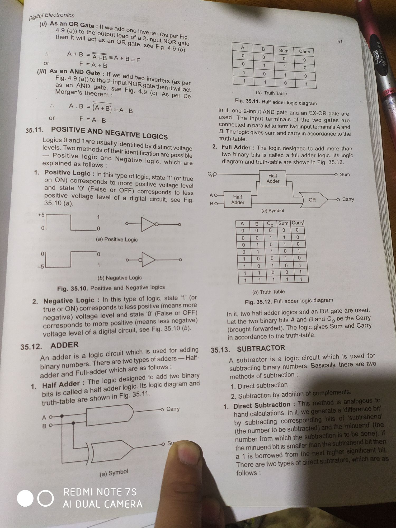
pigital Electronics, , (i) AsanOR Gate - rea, : ad, , 4.9 (a)) to the’ id one j, then it will act output lead of Myerter (as per Fig, n OR “input NO :, Gate, see Fig oe gate, , 9.4.9, A+B === (6)., ~ A+B SA+B=, or F=A+B B=F, (iif) AS an AND Gat, ; fe: If, Fig. 4.9 (a)) to We add two j, , as an aR nae 2-input NOR aoe (@s per, Morgan's hearers See Fig. 4.9 eee itwill act, : » AS per De, , A.B=(AsB) aap, ch F=A.B, , 35.11. POSITIVE AND NEGATIVE totes, , Loa, oa oe lare Usually identified, e ae methods of their identifi, ositive logic and Negati, explained as follows : Te, 1. Positive Logic : | hi, + In this ty, i, , eee Pe of logic, state '1', on 0 to more Positive ae es, (False or OFF) sit ee, , positive voltage lev ) corresponds to less, 35.10 (a). 9) el of a digital circuit, see Fig., +5, , =, , 0 0 —>o—, (a) Positive Logic, , 0 0, , | o—| >——«, , (b) Negative Logic, , by distinct Voltage, cation are possible, logic, which are, , , , a, , Fig. 35.10. Positive and Negative logics, , 2. Negative Logic : In this type of logic, state ‘1’ (or, true or ON) corresponds to less positive (means more, negative) voltage level and state ‘0’ (False or OFF), corresponds to more positive (means less negative), voltage level of a digital circuit, see Fig. 35.10 (b), , 35.12. ADDER, An adder is a logic circuit which is used for adding, binary numbers. There are two types of adders — Halfadder and Full-adder which are as follows, i i d to add two binary, dder : The logic designe’ add, % ee a half adder logic. Its logic diagram and, truth-table are shown in Fig- 35.11., A Carry, B, , (a) Symbol, , 2., , Cp, , , , , , , , Sum,, , , , Carry, , , , , , , , , , , , , , , , , , , , , , Elo Lore, alo]=/o/@, , 9 0, A 0, i 0, o 1, , , , aq, , (b) Truth Table, Fig. 35.11. Half adder logic diagram, , , , , , In it, |, , cere input AND gate and an EX-OR gate are, , a ‘ input terminals of the two gates are, , ae a Parallel to form two input terminals A and, = i" i, , Fees gives sum and carry in accordance to the, fa ope 2 The logic designed to add more than, a inary bits is called a full adder logic. Its logic, lagram and truth-table are shown in Fig. 35.12., , , , , , , , , , , , , , , , , , , , Half © Sum, a Adder, AO™) ait, BO Adder OR Carry, (a) Symbol, A B | Cy [Sum [Carry, 0 0 0 0 0, 0 a 0 1 Al 4 L 0, 0 A 0 i 0, 0 1 1 0 1, 4 0 0 ‘tl 0, 1 0 il 0 4, 1 1 0 0, dl 1 1 fa, (b) Truth Table, , , , , , , , , , , , , , , , , , , , , , , , , , , , , , , , , , , , , , , , , , , Fig. 35.12. Full adder logic diagram, , In it, two half adder logics and an OR gate are used., Let the two binary bits A and B and C, be the Carry, (brought forwarded). The logic gives Sum and Carry, in accordance to the truth-table., , 35.13. SUBTRACTOR, , A subtractor is a logic circuit which is used for, , subtracting binary numbers. Basically, there are two, , methods of subtraction : " eo ”, 4. Direct subtraction, , 2. Subtraction by addi, , 4. Direct Subtraction, , hand calculations. In, , by subtracting corre, , (the number to be subi, , number from which thi, , , , , , , , , , , , There are two types 9, follows : 4
