Page 1 :
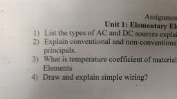
BTES 106/206, Basic Electrical and Electronics Engineering, Audit Course, ======================================================, Course Objectives:, 1. To know and apply basic ideas and principles of electrical engineering., 2. To Identify protection equipment and energy storage devices., 3. To differentiate electrical and electronics domains and explain the operation of diodes and, transistors., 4. To acquire knowledge of digital electronics, 5. To design simple combinational and sequential logic circuits., , Course Outcomes:, Students will be able to:, 1. Apply basic ideas and principles of electrical engineering., 2. Identify protection equipment and energy storage devices., 3. Differentiate electrical and electronics domains and explain the operation of diodes and, transistors., 4. Acquire knowledge of digital electronics, 5. Design simple combinational and sequential logic circuits., , ======================================================, Unit 1: Elementary Electrical Concepts, Syllabus:, Fundamental of Electrical system., Potential difference., Ohm's law., Effect of temperature on elements, Resistance temperature coefficient., Electrical wiring system: Study of different wire gauges and their applications in, domestic and industry., Energy Resources and Utilization: Conventional and nonconventional energy, resources., Introduction to electrical energy generation from different resources, transmission,, distribution and utilization, Advantages & Disadvantages of AC & DC transmission., Concept of Supply Demand, Power Factor, Need of unity power factor., =================================================================, What is mean by Electrical Engineering?, “The branch of engineering which deals with current flowing through conductors only, is called electrical engineering”., Examples of electrical applications: filament lamp, heater, geyser, all types of motors,, fans etc., , What is Electronics Engineering?, “The branch of engineering which deals with current flowing through semiconductors, and vacuum is called electronics engineering”.
Page 2 :
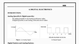
Examples of electronics applications: Television set, DVD player, VCD player,, Cassette player, cell phone, radio receiver etc., Band theory of solids, According to band theory each and every element consists of conduction band and, valance band. Depending upon the relative position of the valence band and the, conduction band, the solids can be classified into conductors, insulators and, semiconductors, Conductors, The conduction band and the valence band partly overlap each other and there is no, forbidden energy band gap in between, The electrons from the valence band can easily move into the conduction band, Hence, large number of electrons are available for conduction, The resistance of such materials is low and conductivity is high, , Insulators, In case of insulators, a large energy gap exists between the valence band and the, conduction band, The energy gap is so high that the electrons from the valence band cannot move to, the conduction band by thermal excitation, As there is no electrons in the conduction band, electrical conduction is not possible, , Semiconductors, A finite but a small energy gap exists between the valence band and the conduction, band, At room temperature, some of the electrons from the valence band acquire energy, and move into the conduction band, Hence, at high temperature, semiconductors have conductivity and resistance is also, not as high as insulators
Page 3 :
Type of Electrical sources: Electrical sources are classified as AC source and DC source., AC (Alternating current): It is defined as the current which keeps changing it's, value or magnitude and direction with respect to time, , AC sources:, , , , , , AC from MSEB, AC Generator, Function Generator, Inverter
Page 4 :
Types of AC supply, Single phase AC Supply (1 ø):, Voltage specification: 230V ±10%, Frequency: 50 Hz, Terminals: Phase, Neutral, Earth, , Three phase ac supply (3 ø): (440V ±10% 50 Hz), Voltage specification: 440V ±10%, Frequency: 50 Hz, Terminals: R Phase, Y Phase, B Phase ( for delta connection), R Phase, Y Phase, B Phase and Neutral (for delta connection), , DC (Direct current): It is defined as the current which changes it's value or, magnitude in a definite time interval but do not change the direction i.e. it is, unidirectional.
Page 5 :
Sources of Direct Current, DC Generator, Solar cell, Battery / cell, Rectifier, , Basic Electrical Parameters:, Voltage: “Potential difference between two points in an electrical circuit is called as, voltage”. Voltage is denoted by letter “V” measured in “volts” using “Voltmeter”., Current: “Flow of charges is called current”. Current is denoted by “I”. Measured in, “Amperes” using “Ammeter”., Resistance: “Opposition to flow of current by a material is called Resistance”., Resistance is denoted by “R”. Measured in “ohms” using “ohm meter”., Ohm's law: Ohm’s law gives the relation between voltage current and resistance. It, states that, “The current through a conductor between any two points is directly, proportional to the voltage across these points, when the resistance of conductor is, constant”., , The Ohm's Law formula or equation is very straightforward. Ohm's law can be, expressed in a mathematical form: V=IR where V= voltage in volts, I= Current in Amps, and R= Resistance in ohms.
Page 6 :
Effect of temperature on elements:, Elements are classified as Metals, Alloy, Semiconductors and Non metals., There are two types of temperature coefficient, PTC (Positive Temperature Coefficient): If the resistance of element increases due, to increase in temperature then we are saying that such element having positive, temperature coefficient. All metals and alloys having positive temperature coefficient, NTC (Negative Temperature coefficient): If the resistance of element decreases due, to increase in temperature then we are saying that such element having negative, temperature coefficient. All semiconductors and nonmetals having negative, temperature coefficient., , What is Temperature Coefficient of Resistance?, “The temperature coefficient of resistance is generally defined as the change in, electrical resistance of a substance with respect to per degree change in temperature.”, So if we look at the electrical resistance of conductors such as gold,aluminium, silver,, copper, it all depends upon the process of collision between the electrons within the, material. When the temperature increases, the process of electron collision becomes, rapid and faster. As a result, the resistance will increase with the rise in temperature of, the, conductor., Relation between Temperature and Resistances, Let us consider a conductor whose resistance at 0°C is R0 and the resistance at a, temperature T°C is RT. The relation between temperature and resistances R0 and RT is, approximately given as, RT = R0 [1+ α (T-T0)];, RT = R0 [1+ α (∆T)], Hence it is clear from the above equation that the change in electrical resistance of any, substance due to temperature depends mainly on three factors –, 1. The value of resistance at an initial temperature., 2. The rise in temperature., 3. The temperature coefficient of resistance α.
Page 7 :
What is a Generator?, A generator is a machine that converts available mechanical energy into electrical, energy. It works on the principle of Faraday’s Law of Electromagnetic Induction., Based on the output obtained, we classify generators as:, AC Generators, DC Generators, AC Generators or Alternators:, AC generator, also known as alternators, is a machine that converts mechanical, energy into electrical energy. The generated electrical energy is in the form of an alternating, current or sinusoidal output waveform. The mechanical energy is usually supplied by steam, turbines, gas turbines and combustion engines., AC generators work on the principle of Faraday’s law of electromagnetic induction, which states that electromotive force -EMF or voltage – is generated in a current-carrying, conductor that cuts a uniform magnetic field. This can either be achieved by rotating a, conducting coil in a static magnetic field, or by rotating the magnetic field that contains the, stationary conductor. The preferred arrangement is to keep the coil stationary because it is, easier to draw induced alternating current from a stationary armature coil than a rotating coil., The generated EMF depends on the number of armature coil turns, magnetic field, strength, and the speed of the rotating field., E=B l V sin (Ɵ), Where, B= magnetic flux density in tesla, l= active length of conductor in meters, v= velocity of conductor in m/s, Ɵ= angle made by the conductor with magnetic flux density, , Working of an AC Generator:, When the coil rotates in magnetic field (produced between the poles of the magnet),, the flux linkage with coil changes continuously. Due to this, an emf is induced in the coil.
Page 8 :
This produces an electric current that flows through the galvanometer and the slip rings and, brushes. The galvanometer swings between positive and negative values. This indicates that, there is an alternating current flowing through the galvanometer. The direction of the induced, current can be identified using Fleming’s Right Hand Rule., Following are a few advantages of AC generators over DC generators:, AC generators can be easily stepped up and stepped down through transformers., Transmission link size might be thinner because of the step-up feature, Losses are relatively lesser than DC machine, Size of the AC generators are relatively smaller than DC generators, Single phase generator: When a single coil is used and rotated in the magnetic field then, such generators are called single phase generators., Three phase generator: When three coils are used and placed 120 degree apart from, each other and rotated in the magnetic field then such generators are called three phase, generators., Electrical Wiring System for 3 Ø supply:, In three phase generators three coils are used which are placed 120 degree from each, other and rotated in the magnetic field which produces three signals whose phase difference, is also 120 degree. While transmitting the signals/power from generator to load center, following wiring methods are used, Three phase six wire system: In this wiring system, voltage across each coil is, transmitted using separate two lines / wires so this system becomes three phase six, wire system. This system requires more length of wires compare with other wiring, systems.
Page 9 :
Three phase four wire system (STAR connection): In this wiring system, see fig (b), one of the end of each coil is made common and neutral wire is stretched out from, this point and line/wire is stretched from another end of each coil so this wiring, system becomes three phase four wire system. This wiring system is also called star, connection. Generally this wiring is used in distribution purpose., Three phase three wire system (DELTA connection): In this wiring system, see fig, (a), end of first coil is connected to start of second, end of second is connected to start, of third and end of third is connected to start of first and three lines/ wires are, stretched out from three junctions so this system becomes three phase three wire, system. This wiring is also called as delta connection. Generally this wiring is used, for transmission purpose., , Electrical Wiring System for 1 Ø supply:, Single phase wiring systems are implemented to control the application in the, following ways., Simple wiring, Stair case wiring, Godown wiring, Simple wiring:, In simple wiring electrical application such as bulb is operated with the help of, switch and protected using fuse. Switch and fuse are always connected in series with bulb in, phase line. Turning on of switch causes bulb on and turning off of switch causes bulb off., Connections are as per shown in diagram
Page 10 :
Stair case wiring:, A two way switch (SPDT) S1 is installed near the first step of the stairs. The other, two way switch (SPDT) S2 is installed at the upper part where the stair ends. The light point, is provided between first and last stair at an adequate location and height. Initially bulb is off, due to discontinuity in supply see fig (a) If the lower switch S1 is operated the bulb turns on, and persons travels from stair start to stair end. Now switch S2 is operated which switch off, the bulb. Same operation is possible while climb down the stairs also., , Godown Wiring:, Godown wiring circuit is needed in tunnel like structures, warehouses, long passages,, big godowns having lots of rooms and different portions., It was the best choice to save electricity and energy consumption where only one load, i.e. light bulb can be operate at a time. Nowadays, as CFL and LED bulb which consumes, low energy, this type of wiring is avoided due to its complexity ignoring the power, consumption., In this wiring installation tutorial, we will be going to control three lights bulbs using one, SPST (Single pole single throw or single way) and two SPDT (Single pole double throw or, two way) switches., , Working:, It is a linear sequence of switching i.e. When a person enter the first room or portion,, all lighting points are switched OFF as the first SPST switch is at OFF position., When he, Switch ON the SPST, the first lamp switch ON., Switch ON the first SPDT, the second lamp switch ON and the previous one switch, OFF., Switch ON the second SPDT, the third lamp switch ON and the previous (second one), lamp switch OFF.
Page 11 :
Wires and their applications:, Single Conductor Wire: Single Conductor wire is the most popular choice for electrical, layout inside a home. It is available in multiple gauges, colour (for phase, neutral and ground, identification) and solid or stranded conductors. A single solid wire provides better, connections but single stranded wires are easier to route through conduits., , Coaxial Cable: Coax or coaxial cable is type of electrical cable made from four layers,, forming coaxial shape (having common axis or centre). The central part of coaxial cable is a, conductor covered by an insulating plastic layer which is surrounded by a metallic shield. On, top that is a fourth layer of plastic insulation., The coaxial cable is used for transmission of high frequency signal. This is why the, metallic shield is used for blocking noise interference. It is commonly used for cable, television signal distribution, signal transmission between antennas, transmitter and receiver., , Twisted Pair Cable: This type of communication cable is made from two insulated wires, twisted together to form a twisted pair. The purpose of twisting is to reduce the, electromagnetic interference or noise. They are used in Ethernet network and telephone, communication., , Fiber Optic Cables: Fiber optic or optical fiber cable is a type of communication cable made, of flexible, transparent glass fibers known as optical fibers that transmit data in the form of, light. The fiber’s thickness is approximately equal to human hair and each individual fiber is, covered with plastic insulation. There is another external protection layer that protects the, fibers from interference.
Page 12 :
Non-Metallic Sheathed Cable (NM, NM-B): The non-metallic or NM sheathed cable or, known by its trademark name “romex” cable is a type of electrical cable whose outer sheath, is made of plastic that protect the inside conductors. It is commonly used for, residential electrical wiring., , Ribbon cable: They are mostly used in electronic devices and computers to connect different, internal peripheral that require data buses like hard drives, CD drives, printers etc. Due to, their flat shape, they block the airflow inside computer which affects the cooling system., Nowadays, they are mostly replaced by round cables.
Page 13 :
Twin-lead: (Antenna wire) Twin lead cable is a two conductor flat cable used as a balanced, line to carry radio frequency RF signal. The conductors are held apart and uniformly space by, a plastic layer between them. The equal spacing is very important because it keeps the signal, from distortion. The conductors are mostly stranded to avoid skin effects and they are, insulated using the same plastic material, ., , Wire gauges and their current rating:, , 1/18 wire means single conductor of 18 gauge., 7/36 wire means seven conductors of 36 gauge each,, 3/18 wire means three conductors of 18 gauge each.
Page 14 :
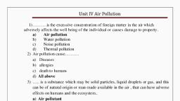
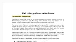
Classification of Energy Sources:, , Classification of Energy Sources, Conventional source, Nonconventional source, What is a conventional source of energy?, • Conventional sources of energy are the natural energy resources which are present in a, limited quantity and are being used for a long time. They are called non-renewable sources as, once they are depleted, they cannot be generated at the speed which can sustain its, consumption rate. They are formed from decaying matter over hundreds of millions of years., • Examples are coal, petroleum product (like oil petrol, diesel, and kerosene), natural gas,, nuclear fuel (like Uranium, thorium, plutonium) and water resources, • 90 % of electrical energy is generated with the help of coal, petroleum product and natural, gas, • 10 % of electrical energy is generated with nuclear fuel., , What is nonconventional source of energy?, • Non-conventional sources of energy are the energy sources which are continuously, replenished by natural processes. These cannot be exhausted easily, can be generated, constantly so can be used again and again., • Examples are solar energy, wind energy, tidal energy, biomass energy, geothermal energy, and ocean thermal etc., • They are called renewable resources.
Page 15 :
Generation, Transmission, Distribution and Utilization:, , Generation: Electricity is most often generated at a power plant by electromechanical, generators. Various types of power plants are used to generate electricity like steam power, plant, Nuclear power plant, hydroelectric power plant, solar power plant, wind power plants, OTEC power plant, Tidal power plant etc., Transmission:, Electrical, power, transmission involves, the, bulk, movement, of electrical energy from a generating site, such as a power station or power plant, to, an electrical substation where voltage is transformed and distributed to consumers or other, substations, Distribution: Electric power distribution is the final stage in the delivery of electric power; it, carries electricity from, the, transmission, system, to, individual, consumers., Primary distribution lines carry this medium voltage power to distribution transformers, located near the customer's premises., Utilization: Utilization is the "end result" of the generation, transmission, and distribution, of electric power. The energy carried by the transmission and distribution system is turned, into useful work, light, heat, or a combination of these items at the utilization point., Advantages and Disadvantages of AC over DC:, Advantages:, (i) The generation of AC is cheaper than that of DC., (ii) When AC is supplied at higher voltages, the transmission losses are small compared to, DC transmission., (iii) AC can easily be converted into DC with the help of rectifiers., Disadvantages:, (i) Alternating voltages cannot be used for certain applications e.g. charging of batteries,, electroplating, electric traction etc., (ii) At high voltages, it is more dangerous to work with AC than DC.
Page 16 :
Concept of Supply Demand:, India is the world's third largest producer and third largest consumer of electricity., The National electric grid in India has an installed capacity of 375.32 GW as of 31, December 2020., Electricity coverage 99.93% (31 March 2019), Share of fossil energy 79.8%, Share of renewable energy 17.3%, Consumption % wise, Residential 24.76 %, Industrial 41.16%, Agriculture17.69%[, Commercial 8.24%, Traction1.52%, Transmission and distribution losses 21.04%, Power factor and need of unity power factor:, Power factor (PF) is the ratio of working power, measured in kilowatts (kW), to, apparent power, measured in kilovolt amperes (kVA). Apparent power, also known as, demand, is the measure of the amount of power used to run machinery and equipment during, a certain period., , The ideal power factor is unity, or one. Anything less than one means that, extra power is required to achieve the actual task at hand. All current flow causes losses both, in the supply and distribution system. A load with a power factor of 1.0 results in the most, efficient loading of the supply., , Please Google to search more study material, ====================================================