Page 1 :
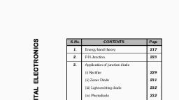
Lecture 24: Doping, , Contents, 1 Introduction, , 1, , 2 Thermal diffusion, 2.1 Diffusion sources . . . . . . . . . . . . . . . . . . . . . . . . ., 2.2 Drive-in . . . . . . . . . . . . . . . . . . . . . . . . . . . . . ., , 2, 5, 6, , 3 Diffusion concentration gradients, 7, 3.1 Constant surface concentration . . . . . . . . . . . . . . . . . 10, 3.2 Constant total dopant . . . . . . . . . . . . . . . . . . . . . . 13, 3.3 Diffusion example . . . . . . . . . . . . . . . . . . . . . . . . . 14, 4 Ion implantation, , 1, , 18, , Introduction, , Doping refers to the addition of specific impurities to a semiconductor to, modify its electrical properties. In microfabrication the commonly used material is silicon. Pure Si (intrinsic Si) is a poor conductor with a negative, temperature coefficient of resistance (i.e. resistance decreases with rise in, temperature) due to thermal generation of electrons and holes. Doping helps, in exponentially increasing the conductivity and also produces a stable, temperature independent, resistance around room temperature. Doped or extrinsic semiconductors can be p or n type depending on the nature of the, impurity atom., The starting wafers in integrated circuit (IC) manufacturing are usually p or, n type doped wafers. To form devices like transistors, diodes, or resistors,, specific regions of the wafer must be doped with specific amounts and types, of impurities. Some examples of doped devices are shown in figure 1. There, are two main methods of doping., 1
Page 2 :
MM5017: Electronic materials, devices, and fabrication, , Figure 1: Schematic of a (a) diode, (b) MOSFET, and (c) BJT. These are, made by adding p and n type dopants to different parts of a base wafer. In, (a) and (b) the base wafer is p type while it is n type in (c)., , 1. Thermal diffusion, 2. Ion implantation, The two methods are summarized in figure 2. As part of the process flow,, there are specific goals that doping should meet, 1. Create a specific concentration of dopant atoms at and below the surface of the wafer, i.e. establish a controlled concentration gradient., 2. Create a junction (pn or np or graded p or n) at a specific depth from, the wafer surface. This is important for MOSFETs since this defines, the channel width. In a BJT, doping is used to define widths of the, emitter, base, and collector regions., 3. Create specific distributions and concentrations of dopants laterally, along the wafer surface. This is related to patterning and is used to, define the smallest lateral region that can be doped., , 2, , Thermal diffusion, , Thermal diffusion is a two step process, similar to the steps in oxidation, process by consuming the underlying Si., 1. Deposition - dopant atoms are introduced at the wafer surface., 2. Drive-in - the dopant atoms then diffuse into the wafer to create the, required concentration gradient., 2
Page 3 :
MM5017: Electronic materials, devices, and fabrication, , Figure 2: Types of doping. (a) Thermal diffusion (b) Ion implantation. In, thermal diffusion, the maximum concentration is at the surface and dopants, diffuse into the wafer. In ion implantation, the dopants are embedded below, the surface. Adapted from Microchip fabrication - Peter van Zant., , 3
Page 4 :
MM5017: Electronic materials, devices, and fabrication, , Figure 3: (a) The stages in thermal diffusion. The dopant atoms are introduced at the wafer surface and they diffuse into the wafer. (b) A cross, section schematic showing the final concentration distribution. Adapted from, Microchip fabrication - Peter van Zant., , 4
Page 5 :
MM5017: Electronic materials, devices, and fabrication, , The two steps are shown schematically in figure 3. While dopant atoms move, vertically into the wafer, there is also a lateral spread. This has implications, for the minimum dimensions of the region that can be doped. In Si, the common dopants are boron for p type and arsenic, antimony, and phosphorus for, n type., , 2.1, , Diffusion sources, , There are different sources for the dopant atoms. These can be solid, liquid,, or gaseous sources. Some examples of dopant materials for Si are, 1. Antimony (Sb) - Sb2 O3 (s), 2. Arsenic (As) - As2 O3 (s), AsH3 (g), 3. Phosphorus (P) - POCl3 (l), P2 O5 (s), PH3 (g), 4. Boron (B) - BBr3 (l), B2 O3 (s), BCl3 (g), A more complete list of sources are shown in table 1., For liquid and gaseous sources, a concentration of the dopant vapor should, Table 1: Some commonly diffusion sources in silicon. The compound and its, state is also included. The use of dopants in different state determines the, shape of the concentration profile within the wafer. Adapted from Microchip, fabrication - Peter van Zant., Type, n-type, , p-type, , Element, Antimony, Arsenic, , Compound, Formula State, Antimony Trioxide, Sb2 O3, solid, Arsenic Trioxide, As2 O3, solid, Arsine, AsH3, gas, Phosphorous Phosphorous oxychloride, POCl3, liquid, Phosphorous Pentoxide, P2 O5, solid, Phosphine, PH3, gas, Boron, Boron Tribromide, BBr3, liquid, Boron Trioxide, B2 O3, solid, Diborane, B2 H6, gas, Boron Trichloride, BCl3, gas, Boron Nitride, BN, solid, , be established at the surface. For a liquid source, a carrier gas is usually, used to transport the vapors to the diffusion furnace. The setup is shown, 5
Page 6 :
MM5017: Electronic materials, devices, and fabrication, , Figure 4: Thermal diffusion setup with a liquid dopant source. A carrier gas, like nitrogen is bubbled through the dopant liquid and the vapor is carried, into the furnace. Oxygen is also used when an oxide surface needs to be, created along with doping. Adapted from Fundamentals of semiconductor, manufacturing and process control - May and Spanos., , in figure 4. A similar arrangement is used for gaseous sources. Here, the, carrier gas is used to dilute the dopant gas to the required concentration., The gas manifold system is shown in figure 5. For solid sources, wafer sized, ”slugs” are packed into the furnace along with the product wafers (e.g. for, boron, boron nitride slugs can be used as solid sources), this is called a solid, neighbor source. An other option is to spin on the oxide source on the wafer, surface using a suitable solvent, typically used for oxide sources. It is also, possible to vaporize the solid source is a neighboring furnace and use a carrier, gas to transport the vapors to the wafer. The use of solid sources in thermal, diffusion is shown in figure 6., , 2.2, , Drive-in, , Once the dopant atoms have arrived on the wafer surface, they need to be, redistributed into the bulk. This process is called drive-in. At the same, time, the carrier gas could also react with the wafer surface, especially if, there is some reactive gas like oxygen (dry ox) or water vapor (wet ox)., These could cause oxidation of the Si along with dopant diffusion. While, this might be desirable under some circumstances, it would also affect dopant, distribution, since the presence of an oxide layer can lead to an increase of, n-type dopants and decrease of p-type dopants, just below the interface. This, is shown in figure 7. The drive-in process requires diffusion of the impurities, into Si. Depending on the relative size of the impurity atom, this can be, either through vacancy diffusion or interstitial diffusion. The interstitial, 6
Page 7 :
MM5017: Electronic materials, devices, and fabrication, , Figure 5: The gas manifold system for a thermal diffusion system. The, dopant gas and inert gas are mixed to get the right dopant concentration., There is also a reaction gas, like oxygen, if an oxide layer also needs to be, formed. Adapted from Microchip fabrication - Peter van Zant., , mechanism is shown in figure 8 while the substitutional mechanism is shown, in figure 9. Boron and Phosphorus are small and diffuse by a dual (vacancy, and interstitial mechanism) while As and Sb predominantly diffuse by the, vacancy mechanism., , 3, , Diffusion concentration gradients, , The amount of impurities that can be incorporated in Si depends on the, solid solubility. This depends on the impurity atom and temperature, given, by figure 10. To calculate the concentration of the impurities as a function, of depth from the wafer surface, Fick’s laws of diffusion can be used. Fick’s, first law is written as, ∂c(x, t), (1), J = −D, ∂x, where J is the flux of impurity atoms, which is a constant with respect to, time (steady state diffusion) and c(x, t) is the concentration at depth x and, time t and D is the diffusion coefficient. D is temperature dependent and is, , 7
Page 8 :
MM5017: Electronic materials, devices, and fabrication, , Figure 6: Solid sources for thermal diffusion can be either (a) remote or (b), neighbor sources. In a remote source the solid is vaporized and the vapors, are passed into the furnace. In neighbor sources, the solid is loaded in the, furnace along with the wafers. Both sources produce different concentration, profiles in the wafer. Adapted from Microchip fabrication - Peter van Zant., , 8
Page 9 :
MM5017: Electronic materials, devices, and fabrication, , Figure 7: Growth of oxide layer on Si can cause (a) pile-up of n type impurities and (b) depletion of p type impurities. The oxide layer can be grown, along with dopant diffusion or once diffusion is complete. Adapted from, Microchip fabrication - Peter van Zant., , Figure 8: Interstitial diffusion mechanism showing motion of dopant atom, from position in (a) to (b). Here, the dopant atom is smaller than the silicon, atom, so that interstitial doping is possible. Adapted from VLSI fabrication, principles - S.K. Ghandhi, , 9
Page 10 :
MM5017: Electronic materials, devices, and fabrication, , Figure 9: Substitutional diffusion mechanism showing motion of dopant atom, from position in (a) to (b). Substitutional diffusion happens when the dopant, size is comparable to the Si atom. Adapted from VLSI fabrication principles, - S.K. Ghandhi, , given by, D = D0 exp(−, , Ea, ), kB T, , (2), , where D0 is the pre-exponent factor and Ea is the activation energy for, diffusion. For unsteady state, with the flux varying with time and position,, a more general equation is Fick’s second law, given by, ∂c(x, t), ∂J(x, t), ∂ 2 c(x, t), = −, = D, ∂t, ∂x, ∂x2, , (3), , The assumption is that D is not a function of concentration. By applying, equations 1 and 3, it is possible to calculate the concentration gradient under, various conditions. The maximum amount of dopants that can be incorporated is given by the impurity solubility shown in 10. This represents the, thermodynamic limit. There are two common doping conditions that exist, in thermal diffusion., , 3.1, , Constant surface concentration, , For gaseous and liquid sources, there is a constant concentration of impurities, at the surface. There is a vapor of impurity atoms (it is also true for a solid, source with remote evaporation) that maintains the constant concentration, on the surface. Also, the diffusion length is much smaller than the wafer, thickness so that the wafer can be approximated as a semi-infinite solid. In, , 10
Page 11 :
MM5017: Electronic materials, devices, and fabrication, , Figure 10: Solid solubility of various impurities in Si as a function of T., Commonly used p and n dopants have high solubility, approaching the level, of degenerate semiconductors. Other impurities like metals and oxygen have, solubility levels of a few ppm. Adapted from Microchip fabrication - Peter, van Zant., , 11
Page 12 :
MM5017: Electronic materials, devices, and fabrication, , Figure 11: Concentration profiles for constant surface concentration with increasing time. The maximum concentration is at the surface. With increasing, time, the junction depth goes deeper within the wafer. The junction depth, is defined as when the dopant concentration becomes equal to the wafer bulk, doping level. In this case, the bulk dopant concentration is 1013 cm−3 . The, plot was generated in MATLAB., , this case, the impurity concentration, C(x, t), is given by, x, C(x, t) = Cs erfc( √ ), 2 Dt, , (4), , where Cs is the surface concentration and erfc is the complementary error, function., Consider an example of diffusion under a constant surface concentration, of 1019 cm−3 and a bulk dopant concentration of 1013 cm−3 . The wafer, temperature is 1000 K, and the diffusion coefficient at this temperature is, 2.9 × 10⁻²² m2 s−1 . The error function solution, for this system, is plotted in, figure 11, for three different times, 15, 30, and 60 minutes. Equation 4 can, also be used to calculate the junction depth for a pn diode. If the base wafer, is p type with concentration Cp , the junction depth (where electron and hole, concentration is the same) by n type impurity diffusion is given by, xpn, Cp, = erfc( √ ), Cs, 2 Dt, , (5), , where xpn is the junction location.With increasing time, the junction depth, increases., , 12
Page 13 :
MM5017: Electronic materials, devices, and fabrication, , Figure 12: Comparison of (a) and (c) error function solution and (b) and (d), Gaussian solution to the diffusion equations, for different diffusion lengths., Compared to the error function solution, the slope of the Gaussian solution, is less steep. Thus, there is greater penetration of the dopants in the bulk,, with respect to the surface concentration, for the same diffusion length. Plot, was generated using MATLAB., , 3.2, , Constant total dopant, , In this scenario, the total amount of dopant atoms at the start of the diffusion process is a constant and the concentration of the atoms at the surface, gradually decreases with time. This happens in the case of doping from a, solid source that is placed close to the wafer (either solid slugs close to the, wafer or dopants spun on the wafer surface). Let QT be the total amount, of dopants on the surface (at start of diffusion) per unit area. Then, the, concentration, C(x, t), is given by, x2, QT, exp(−, ), C(x, t) = √, 4Dt, πDt, , (6), , This is a Gaussian function, in contrast to the error function solution for, a constant surface concentration. The change in surface concentration as a, function of time can be obtained from equation 6 with x = 0. This gives, QT, C(0, t) = √, πDt, The error function and Gaussian solutions are compared in figure 12., , 13, , (7)
Page 14 :
MM5017: Electronic materials, devices, and fabrication, Table 2: Diffusion parameters for different impurities in Si, Parameter, D0 (cm2 s−1 ), Ea (eV ), , 3.3, , B, P As, 0.76 3.85 24, 3.46 3.66 4.1, , Sb, 0.214, 3.65, , Diffusion example, , Consider a n-type Si wafer with As concentration of 1016 cm−3 . A pn junction, is to be formed by diffusing p-type impurity, using a solid boron source., The diffusion is to be carried out at 1000 K. The diffusion coefficients for, various dopants in Si, as a function of temperature, are shown in figure 13., Extrapolating from figure 13, the diffusion coefficient of B in Si at 1000, K is 2.9 × 10⁻¹⁸ cm2 s−1 . The diffusion coefficient can also be calculated, from known values of pre-exponent factor (D0 ), which is 0.76 cm2 s−1 , and, activation energy, which is (Ea ) is 3.46 eV for B in Si, using equation 2., Since B is a solid source, this is a case of constant total dopant concentration,, discussed in section 3.2. Hence, the concentration as√a function of depth, and time, C(x, t), is given by equation 6. The term 4Dt represents the, diffusion length for two-dimensional diffusion. Let QT be 1013 atoms cm−2 ,, is the total surface concentration per unit area at the start of the process., Using equation 6, it is possible to calculate the junction depth after a certain, time, say t = 2 hrs. Junction depth, xpn , is defined at the depth when the n, and p concentrations are equal. At 2 hrs, and at 1100 ◦ C, the depth, xpn is, calculated to be 8.3 nm, represents a shallow junction., To increase the junction depth (for the same time), the diffusion coefficient, has to be increased. One way to achieve this, is by increasing temperature., For a temperature of 1200 K, the value of D is 2.3 × 10⁻¹⁵ cm2 s−1 . This, translates, using equation 6, into a junction depth of 180 nm., A combination of error function and Gaussian diffusion profiles is used for, forming transistor junctions, e.g. BJT junction shown in figure 1. In this, case, the first layer is formed by diffusion from a solid source (Gaussian, profile) followed by diffusion from liquid or gas source (erf profile), as shown, in figure 14. The intersection points for the two concentration profiles and the, point where the Gaussian profile intersects the base dopant concentration,, represent the junction locations. This is shown in figure 15. The dopant, profiles will get affected with any subsequent annealing steps. Pre-exponent, factors and activation energies for different dopants in Si are listed in table, 2., , 14
Page 15 :
MM5017: Electronic materials, devices, and fabrication, , Figure 13: Diffusion coefficients as a function of temperature for different impurities in Si. This is a semi log plot of concentration vs. inverse temperature, and the slope gives the activation energy. Adapted from VLSI fabrication, principles - S.K. Ghandhi, , 15
Page 16 :
MM5017: Electronic materials, devices, and fabrication, , Figure 14: Concentration profiles for multiple diffusion sources. The Gaussian profile is less steep than the error function solution. The intersection, of the two profiles and the intersection of the Gaussian profile with the bulk, doping level represent the positions of the junctions. Adapted from Microchip, fabrication - Peter van Zant., , 16
Page 17 :
MM5017: Electronic materials, devices, and fabrication, , Figure 15: (a) Concentration profiles from a solid and liquid/gas source, (b) Net dopant concentration as a function of depth (c) Formation of a, BJT resulting from the dopant concentration in (b). Adapted from VLSI, fabrication principles - S.K. Ghandhi, , 17
Page 18 :
MM5017: Electronic materials, devices, and fabrication, , Figure 16: Lateral diffusion below an oxide window for (a) constant source, diffusion (b) depleting source diffusion. Lateral diffusion increases with diffusion length, either increase in D or t. Adapted from VLSI fabrication, principles - S.K. Ghandhi, , 4, , Ion implantation, , The biggest limitation of thermal diffusion is that the process is isotropic i.e., lateral diffusion cannot be avoided, though diffusion coefficients in different, crystallographic directions might be different. Thus, an oxide window that, serves as a mask to protect certain regions of the wafers, can be ineffective due, to lateral diffusion. This is shown in figure 16. This is especially important, for doping small regions (due to device miniaturization). Doping control, is also difficult to achieve due to presence of concentration gradients. These, gradients will change in subsequent annealing steps. Thus, there is a thermal, budget associated with doping., 18
Page 19 :
MM5017: Electronic materials, devices, and fabrication, , Ion implantation is a relatively newer doping technique that operates close to, room temperature. It is a physical process of doping, not based on a chemical, reaction. Since ion implantation takes place close to room temperature, it is, compatible with conventional lithographic processes, so small regions can be, doped. Also, since temperature is low, lateral diffusion is negligible., In ion implantation, dopant atoms are ionized, isolated, accelerated and made, to impinge on the wafer surface. These atoms penetrate some depth into the, material and get embedded into the wafer. The schematic of the process, is shown in figure 17. The source material is usually in the form of a gas, e.g. AsH3 , PH3 , and BF3 are some common sources. Similarly, elemental, sources like As and P are also used as solid sources. Electron bombardment, is used to create ions. The ions are then separated using a mass analyzer,, which is a 90◦ magnet, which bends the ions depending on the mass. After, selection, the desired ions are then accelerated and made to impinge on the, wafer surface. Beam scanning or rastering is also possible using electric field, coils to deflect the ion beams., The penetration depth of the ions depend on their energy (changed by the, accelerating field). The concentration profile for ion implantation is shown, in figure 18. The maximum concentration is at a certain depth below the, surface, called range. In thermal diffusion, the maximum concentration, is at the surface and the concentration decreases with depth. The range, depends on the ion type and the energy, as shown in figure 19. There are, two stopping mechanisms - the nucleus of the wafer atoms and the interaction, of the positive ions with the electrons. In ion implantation, the beam density, (# ions/cm2 ), ion energy, and orientation of the wafer matter., In ion implantation, since the wafer surface is impacted by high energy ions,, it can cause damage by knocking Si atoms from their position, causing local, structural damage. This needs a a post thermal annealing treatment to repair, the damage. There are two ways of doing this., 1. Tube furnace - low temperature annealing (600-1000 ◦ C). To minimize, lateral diffusion., 2. Rapid thermal annealing - higher temperatures are possible but for, shorter times., Ion implantation is especially useful with device scaling. It can be used, to create shallow junctions, by having a small range. It can also be used, to dope small regions. It is usually used later in the process flow when, thermal budgets are tight and the high temperature of thermal diffusion is, not allowed., , 19
Page 20 :
MM5017: Electronic materials, devices, and fabrication, , Figure 17: Schematic of the ion implantation process. Dopant atoms are, ionized by bombarding with electrons. These are then isolated, accelerated,, and then impinged on the wafer. There is also a scanning system that allows, the ion beam to scan over the wafer surface. Adapted from Fundamentals of, semiconductor manufacturing and process control - May and Spanos., , 20
Page 21 :
MM5017: Electronic materials, devices, and fabrication, , Figure 18: Concentration profile for ion implantation. The maximum concentration is below the wafer surface, unlike thermal diffusion, and the depth, increases with the ion energy. Adapted from Microchip fabrication - Peter, van Zant., , Figure 19: Plot of the range (penetration depth) vs. ion energy for three, different dopants, i.e P, As, and S. Channeling effects are shown for S, marked, SA and SB . Adapted from Microchip fabrication - Peter van Zant., , 21


