Page 1 :
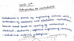
Mechatronics (15ME54T), , UNIT 1, MECHATRONICS, SENSORS AND TRANSDUCERS, Introduction to Mechatronics Systems - Measurement Systems - Control Systems –Sensors and, Transducers - Performance Terminology - Sensors for-Displacement, Velocity, Force, Fluid, Pressure, Liquid Flow, Liquid Level, Temperature, Light Sensors, Selection of Sensors., Course outcome: Discuss the importance of mechatronics systems and know the, usage of Sensors and Transducers for automation applications, Introduction to Mechatronics Systems, The term Mechatronics was ‘invented’ by a Japanese engineer in 1969, as a, combination of ‘mecha’ from mechanisms and ‘tronics’ from electronics. The word now has a, wider meaning, being used to describe a philosophy in engineering technology in which there, is a coordinated, and concurrently developed, integration of mechanical engineering with, electronics and intelligent computer control in the design and manufacture of products and, processes., As a result, Mechatronic products have many mechanical functions replaced with, electronic ones. This results in much greater flexibility, easy redesign and reprogramming,, and the ability to carry out automated data collection and reporting., Definition of Mechatronics, Mechatronics can be defined as an interdisciplinary approach to engineering design, through an integration of mechanical engineering, electrical engineering, computer, technology, electronics and control engineering, Examples:, Truck smart suspension system-Its suspension adjusts to uneven loading conditions,, camera, robots, auto guided vehicle, fax machines, printers, washers, dryers etc., Importance, The manufacturing industries totally depend on integration of, computer science,, electronics technologies for better products and processes. As situation became competitive, it, was necessary to combine electronics & mechanical Engg. Therefore, Mechatronics is also, called as electromechanical systems or control automotive Engg. Mechatronics technology, helps on lowering development costs, reduce risk, produce high quality products., In the design of cars, robots, machine tools, washing machines, cameras and very, many other machines, such an integrated and interdisciplinary approach to engineering design, is increasingly being adopted., Mechatronics brings together areas of technology involving sensors and measurement, systems, drive and actuation systems, and microprocessor., 1. It makes the system more reliable, 3. It makes the system more controlled, 2. It makes the system more flexible, 4. It makes the system cheaper, , Sandur Polytechnic, , Page 1, , Department of Mechanical Engineering
Page 2 :
Mechatronics (15ME54T), The basic elements of a mechatronic system, , System, In designing mechatronic systems, one of the steps involved is the creation of a model, of the system so that predictions can be made regarding its behaviour when inputs occur. Such, models involve drawing block diagrams to represent systems., Definition: A system can be thought of as a box or block diagram which has an input, and an output and where we are concerned not with what goes on inside the box but with only, the relationship between the output and the input., Example:, 1. A spring can be considered as a system to have an input of a force F and an output of, an extension x., 2. A Motor can be considered as a system to have an input Electric power P and an, output of Rotation RPM., , 3. A measurement system can be thought of as a box which is used for making, measurements. It has as its input the quantity being measured and its output the value, of that quantity., For example, a temperature measurement system, i.e., a thermometer, has an input of, temperature and an output of a number on a scale, , Sandur Polytechnic, , Page 2, , Department of Mechanical Engineering
Page 3 :
Mechatronics (15ME54T), Elements of Measurement system, , 1. A sensor responds to the quantity being measured by giving as its output a signal, which is related to the quantity. For example, a thermocouple is a temperature sensor., The input to the sensor is a temperature and the output is an e.m.f., which is related to, the temperature value., 2. A signal conditioner takes the signal from the sensor and manipulates it into a, condition which is suitable either for display or, in the case of a control system, for use, to exercise control. Thus, for example, the output from a thermocouple is a rather, small e.m.f. and might be fed through an amplifier to obtain a bigger signal., 3. A display system displays the output from the signal conditioner. This might, for, example, be a pointer moving across a scale or a digital readout, Control system, A control system can be thought of as a system which can be used to:, 1. Control some variable to some particular value, e.g., a central heating system where, the temperature is controlled to a particular value;, 2. Control the sequence of events, e.g., a washing machine where when the dials are set, to, say, ‘white’ and the machine is then controlled to a particular washing cycle, i.e.,, sequence of events, appropriate to that type of clothing;, 3. Control whether an event occurs or not, e.g., a safety lock on a machine where it, cannot be operated until a guard is in position., , Sandur Polytechnic, , Page 3, , Department of Mechanical Engineering
Page 4 :
Mechatronics (15ME54T), Consider an example of a control system with which we are all individually involved., Your body temperature, unless you are ill, remains almost constant regardless of whether you, are in a cold or hot environment. To maintain this constancy your body has a temperature, control system. If your temperature begins to increase above the normal you sweat, if it, decreases you shiver. Both these are mechanisms which are used to restore the body, temperature back to its normal value., , Types of control sytem, 1. Open loop system, , 2. Closed loop sytem, , Open loop system, A control system without a feedback unit is called Open loop system., , Open-loop systems have the advantage of being relatively simple and consequently, low cost with generally good reliability. However, they are often inaccurate since there is no, correction for error., , Sandur Polytechnic, , Page 4, , Department of Mechanical Engineering
Page 5 :
Mechatronics (15ME54T), Closed loop sytem, A control system with a feedback unit is called closed loop system. The control action, is carried out by the feedback control. Closed-loop systems have the advantage of being, relatively accurate in matching the actual to the required values., They are, however, more complex and so more costly with a greater chance of, breakdown as a consequence of the greater number of components., , Basic elements of a closed-loop system, Comparison element, This compares the required or reference value of the variable condition being controlled with, the measured value of what is being achieved and produces an error signal., error signal = reference value signal - measured value signal, Control element, This decides what action to take when it receives an error signal. It maybe, for, example, a signal to operate a switch or open a valve., Correction element, The correction element produces a change in the process to correct or change the, controlled condition., Process element, The process is what is being controlled. It could be a room in a house with its temperature, being controlled or a tank of water with its level being controlled., Measurement element, The measurement element produces a signal related to the variable condition of the process, that is being controlled., , Sandur Polytechnic, , Page 5, , Department of Mechanical Engineering
Page 6 :
Mechatronics (15ME54T), Sensors and Transducers, Sensors and Transducer, The term sensor is used for an element which produces a signal relating to the quantity, being measured. Thus, in the case of an electrical resistance temperature element, the quantity, being measured is temperature and the sensor transforms an input of temperature into a, change in resistance., The term transducer is often used in place of the term sensor. Transducers are defined, as elements that when subject to some physical change experience a related change. Thus,, sensors are transducers. However, a measurement system may use transducers, in addition to, the sensor, in other parts of the system to convert signals in one form to another form., Selection of sensors, 1. Nature and measurement required, 2. Nature of output required from the sensor, 3. Identification of sensor based on accuracy, range, power, life, cost,, Performance terminology used for sensors & transducers, 1. Range and span, The range of a transducer defines the limits between which the input can vary. The, span is the maximum value of the input minus the minimum value., Thus, for example, a load cell for the measurement of forces might have a, range of 0 to 50 kN and a span of 50 kN., 2. Error: It is the difference b/n the result of the measurement & the true value of the, quantity being measured., Error = Measured value - True value., Thus, if a measurement system gives a temperature reading of 25°C when the actual, temperature is 24°C, then the error is +1°C. If the actual temperature had been 26°C, then the error would have been -1°C., 3. Accuracy: It is the closeness of the measured value with the true value. It is the, summation of all possible errors that are likely to occur as well as the accuracy to, which transducer has been calibrated, 4. Precision: It is the repeatability of the measuring instrument., 5. Sensitivity: It is the ratio output to the input. It is the relationship indicating how, much output you get per unit input., , Sandur Polytechnic, , Page 6, , Department of Mechanical Engineering
Page 7 :
Mechatronics (15ME54T), 6. Hysteresis error: Transducers can, give different output for the same, value of quantity being measured,, whether the value has been reached, by a continuously increasing, change/decreasing change. This, effect is called hysteresis & the, error is called hysteresis error., 7. Non linearity error: The linear relationship b/n input & output is assumed over the, working range for many transducers., 8. Repeatability/Reproducibility: This describes its ability to give the same output for, repeated application of the same input value., , 9. Stability: It is the ability to give same output when used to measure a constant input, over a period of time., 10. Dead band/dead time: It is the range of transducer input values for which there is no, output., 11. Resolution: when the input varies continuously over the range, the output signals for, some sensors may change in small steps. It is the smallest change in the input value, that produces observable changes in the output., 12. Output impedance: When a sensor giving an electrical output is interfaced with an, electronic circuit. It is necessary to know the string opposition of the flow of current is, called output impedance., Classify the sensors & transducers, Sensors are classified according to their nature type of input applications:, 1. Displacement & position sensors-potentiometer sensor, capacitive element, strain, gauge., 2. Pneumatic sensors, 7. Tactile sensor, 3. Hall effect transducer, 8. Light sensors., 4. Eddy current proximity sensor., 9. Velocity & motion sensors, 5. Magnetic switches., 10. Photonic sensors, 6. Photo electric sensors., , Sandur Polytechnic, , Page 7, , Department of Mechanical Engineering
Page 8 :
Mechatronics (15ME54T), Sensors for-Displacement and position, Displacement sensors are concerned with the measurement of the amount by which, some object has been moved; position sensors are concerned with the determination of the, position of some object in relation to some reference point., Displacement and position sensors can be grouped into two basic types:, Contact sensors in which the measured object comes into mechanical contact with the, sensor. Non-contacting where there is no physical contact between the measured object and, the sensor., Potentiometer sensor, , A potentiometer consists of a resistance element with a sliding contact which can be, moved over the length of the element. Such elements can be used for linear or rotary, displacements, the displacement being converted into a potential difference., The rotary potentiometer consists of a circular wire-wound track or a film of, conductive plastic over which a rotatable sliding contact can be rotated. The track may be a, single turn or helical., , With a constant input voltage Vs, between terminals 1 and 3, the output voltage Vo, between terminals 2 and 3 is a fraction of the input voltage, the fraction depending on the, ratio of the resistance R23 between terminals 2 and 3 compared with the total resistance R13, between terminals 1 and 3, i.e., Vo/Vs = R23/R13. If the track has a constant resistance per, unit length, i.e., per unit angle, then the output is proportional to the angle through which the, slider has rotated. Hence an angular displacement can be converted into a potential difference., , Sandur Polytechnic, , Page 8, , Department of Mechanical Engineering
Page 9 :
Mechatronics (15ME54T), Strain gauged element, The electrical resistance strain gauge is a metal wire, metal foil strip or a strip of, semiconductor material which is wafer-like and can be stuck onto surfaces like a postage, stamp. When subject to strain, its resistance R changes, the fractional change in resistance, ∆R/R being proportional to the strain e, i.e.,, , where Ge, the constant of proportionality, is termed the gauge factor., Since strain is the ratio (change in length/original length) then the resistance change of, a strain gauge is a measurement of the change in length of the element to which the strain, gauge is attached., , When the flexible element is bent or deformed as a result of forces being applied by a, contact point being displaced, then the electrical resistance strain gauges mounted on the, element are strained and so give a resistance change which can be monitored. The change in, resistance is thus a measure of the displacement or deformation of the flexible element., Capacitive linear displacement sensors, Capacitive sensors for the monitoring of linear displacements might thus take the forms, shown in Figure 2.8. In, (a) one of the plates is moved by the displacement so that the plate separation changes; in (b), the displacement causes the area of overlap to change; in (c) the displacement causes the, dielectric between the plates to change., , Sandur Polytechnic, , Page 9, , Department of Mechanical Engineering
Page 10 :
Mechatronics (15ME54T), Push pull displacement sensor, This has three plates with the upper, pair forming one capacitor and the lower, pair another capacitor. The displacement, moves the central plate between the two, other plates. The result of, for example, the, central plate moving downwards is to, increase the plate separation of the upper, capacitor and decrease the separation of, the lower capacitor. We thus have When, C1 is in one arm of an a.c. bridge and C2, in the other, then the resulting out-ofbalance voltage is proportional to x. Such a, sensor is typically used for monitoring, , displacements from a few millimetres to, hundreds of millimetres. Non-linearity and, hysteresis are about 60.01% of full range., , Capacitive proximity sensor, One form of capacitive proximity, sensor consists of a single capacitor plate, probe with the other plate being formed by, the object, which has to be metallic and, earthed. As the object approaches so the, ‘plate separation’ of the capacitor changes,, becoming significant and detectable when, the object is close to the probe., Linear variable differential transformer (LVDT), , The linear variable differential transformer, generally referred to by the acronym, LVDT, consists of three coils symmetrically spaced along an insulated tube. The central coil, is the primary coil and the other two are identical secondary coils which are connected in, series in such a way that their outputs oppose each other. A magnetic core is moved through, the central tube as a result of the displacement being monitored When there is an alternating, voltage input to the primary coil, alternating e.m.f. are induced in the secondary coils., Sandur Polytechnic, , Page 10, , Department of Mechanical Engineering
Page 11 :
Mechatronics (15ME54T), With the magnetic core central, the amount of magnetic material in each of the, secondary coils is the same. Thus, the e.m.f. induced in each coil are the same. Since they are, so connected that their outputs oppose each other, the net result is zero output. However,, when the core is displaced from the central position there is a greater amount of magnetic core, in one coil than the other, e.g., more in secondary coil 2 than coil 1. The result is that a greater, e.m.f. is induced in one coil than the other. There is then a net output from the two coils., Since a greater displacement means even more core in one coil than the other, the output, the, difference between the two e.m.f. increases the greater the displacement being monitored., Eddy Current Proximity Sensor, , If a coil is supplied with an alternating current, an alternating magnetic field is, produced. If there is a metal object in close proximity to this alternating magnetic field, then, eddy currents are induced in it. The eddy currents themselves produce a magnetic field. This, distorts the magnetic field responsible for their production. As a result, the impedance of the, coil changes and so does the amplitude of the alternating current. At some preset level, this, change can be used to trigger a switch. Figure shows the basic form of such a sensor; it is, used for the detection of non-magnetic but conductive materials. They have the advantages of, being relatively inexpensive, small in size, with high reliability, and can have high sensitivity, to small displacements., Optical Encoders, An encoder is a device that provides a digital output as a result of a linear or angular, displacement. Position encoders can be grouped into two categories:, 1. Incremental encoders, which detect changes in rotation from some datum position, 2. Absolute encoders, which give the actual angular position, Incremental encoders, , Sandur Polytechnic, , Page 11, , Department of Mechanical Engineering
Page 12 :
Mechatronics (15ME54T), A beam of light passes through slots in a disc and is detected by a suitable light sensor., When the disc is rotated, a pulsed output is produced by the sensor with the number of pulses, being proportional to the angle through which the disc rotates. Thus, the angular position of, the disc, and hence the shaft rotating it, can be determined by the number of pulses produced, since some datum position., In practice three concentric tracks with three sensors are used the inner track has just, one hole and is used to locate the ‘home’ position of the disc. The other two tracks have a, series of equally spaced holes that go completely round the disc but with the holes in the, middle track offset from the holes in the outer track by one-half the width of a hole. This, offset enables the direction of rotation to be determined. In a clockwise direction the pulses in, the outer track lead those in the inner; in the anti-clockwise direction they lag. The resolution, is determined by the number of slots on the disc. With 60 slots in 1 revolution then, since 1, revolution is a rotation of 360°, the resolution is 360/60= 6°., Absolute encoders, This gives an output in the form of a binary number of several digits, each such, number representing a particular angular position. The rotating disc has three concentric, circles of slots and three sensors to detect the light pulses. The slots are arranged in such a, way that the sequential output from the sensors is a number in the binary code. Typical, encoders tend to have up to 10 or 12 tracks. The number of bits in the binary number will be, equal to the number of tracks. Thus with 10 tracks there will be 10 bits and so the number of, positions that can be detected is 210, i.e., 1024, a resolution of 360/1024 = 0.35°., , Proximity switches, There are different types of switches like lever operated, roller type, cam operated, switch which can be activated by the presence of an object io order to give proximity sensor, with o/p ON/OFF. These are simple in construction, easy operation, less space, good, accuracy., , Sandur Polytechnic, , Page 12, , Department of Mechanical Engineering
Page 13 :
Mechatronics (15ME54T), Reed switch, It consists of two magnetic switch contacts sealed in a glass tube. When a magnet is, brought close to the switch, the magnetic reeds are attracted to each other and close the switch, contacts. It is a non-contact proximity switch. Such a switch is very widely used for checking, the closure of doors., , Pneumatic sensors, Pneumatic sensors involve the use of compressed air, displacement or the proximity of, an object being transformed into a change in air pressure. Low-pressure air is allowed to, escape through a port in the front of the sensor. This escaping air, in the absence of any closeby object, escapes and in doing so also reduces the pressure in the nearby sensor output port., However, if there is a close-by object, the air cannot so readily escape and the result is that the, pressure increases in the sensor output port. The output pressure from the sensor thus depends, on the proximity of objects. Such sensors are used for the measurement of displacements of, fractions of millimeters in ranges which typically are about 3 to 12 mm., , Photosensitive sensors, Photosensitive devices can be used to, detect the presence of an opaque object by, its breaking a beam of light, or infrared, radiation, falling on such a device or by, detecting the light reflected back by the, object., , Sandur Polytechnic, , Page 13, , Department of Mechanical Engineering
Page 14 :
Mechatronics (15ME54T), , Hall effect sensors, Hall, Effect, Sensors consist, basically of a thin piece of rectangular ptype semiconductor material passing a, continuous current through itself. When, the device is placed within a magnetic, field, the magnetic flux lines exert a force, on the semiconductor material which, deflects the charge carriers, electrons and, holes, to either side of the semiconductor, slab. This movement of charge carriers is a, result of the magnetic force they, experience, passing, through, the, semiconductor material., As these electrons and holes move side wards a potential difference is produced, between the two sides of the semiconductor material by the build-up of these charge carriers., Then the movement of electrons through the semiconductor material is affected by the, presence of an external magnetic field which is at right angles to it and this effect is greater in, a flat rectangular shaped material., Generally, Hall Effect sensors and switches are designed to be in the “OFF”, (open, circuit condition) when there is no magnetic field present. They only turn “ON”, (closed, circuit condition) when subjected to a magnetic field of sufficient strength and polarity., Velocity sensors, Tachogenerator, The tachogenerator is used to, measure angular velocity., One form, the variable reluctance, tachogenerator, consists of a toothed wheel, of ferromagnetic material which is, attached to the rotating shaft. A pick-up, coil is wound on a permanent magnet. As, the wheel rotates, so the teeth move past, the coil and the air gap between the coil, and the ferromagnetic material changes., We have a magnetic circuit with an air gap, which periodically changes. Thus, the flux, linked by a pick-up coil change. The, , Sandur Polytechnic, , Page 14, , resulting cyclic change in the flux, produces an alternating e.m.f. in the coil., , Department of Mechanical Engineering
Page 15 :
Mechatronics (15ME54T), , AC generator form of Tachogenerator, , It consists of a coil, termed the rotor,, which rotates with the rotating shaft. This, coil rotates in the magnetic field produced, by a stationary permanent magnet or, electromagnet and so an alternating e.m.f., is induced in it. The amplitude or, , frequency of this alternating e.m.f. can be, used as a measure of the angular velocity, of the rotor. The output may be rectified to, give a d.c. voltage with a size which is, proportional to the angular velocity. Nonlinearity for such sensors is typically of the, order of 60.15% of the full range and the, sensors are typically used for rotations up, to about 10 000 rev/min., , Force sensor, A spring balance is an example of a, force sensor in which a force, a weight, is, applied to the scale pan and causes a, displacement, i.e., the spring stretches. The, displacement is then a measure of the, force., , Strain gauge load cell, A very commonly used form of, force-measuring transducer is based on the, use of electrical resistance strain gauges to, monitor the strain produced in some, member when stretched, compressed or, bent by the application of the force. The, arrangement is generally referred to as a, load cell. Figure shows an example of such, a cell. This is a cylindrical tube to which, strain gauges have been attached. When, forces are applied to the cylinder to, compress it, then the strain gauges give a, resistance change which is a measure of, the strain and hence the applied forces., , Sandur Polytechnic, , Page 15, , Department of Mechanical Engineering
Page 16 :
Mechatronics (15ME54T), , Fluid pressure sensors, Many of the devices used to monitor fluid pressure in industrial processes involve the, monitoring of the elastic deformation of diaphragms, capsules, bellows and tubes., The types of pressure measurements that can be required are: absolute pressure where, the pressure is measured relative to zero pressure, i.e., a vacuum, differential pressure where a, pressure difference is measured and gauge pressure where the pressure is measured relative to, the barometric pressure., , For a diaphragm (Figure a and b), when there is a difference in pressure between the, two sides then the centre of the diaphragm becomes displaced. Corrugations in the diaphragm, result in a greater sensitivity. This movement can be monitored by some form of displacement, sensor, e.g., a strain gauge, as illustrated in Figure., , A specially designed strain gauge is often used, consisting of four strain gauges with, two measuring the strain in a circumferential direction while two measure strain in a radial, direction. The four strain gauges are then connected to form the arms of a Wheatstone bridge., While strain gauges can be stuck on a diaphragm, an alternative is to create a silicon, diaphragm with the strain gauges as specially doped areas of the diaphragm. Such an, arrangement is used with the electronic systems for cars to monitor the inlet manifold, pressure., Capsules (Figure (a)) can be considered to be just two corrugated diaphragms, combined and give even greater sensitivity. A stack of capsules is just a bellows (Figure (b)), and even more sensitive. Figure shows how a bellows can be combined with an LVDT to give, a pressure sensor with an electrical output. Diaphragms, capsules and bellows are made from, such materials as stainless steel, phosphor bronze and nickel, with rubber and nylon also, being used for some diaphragms. Pressures in the range of about 103 to 108 Pa can be, monitored with such, sensors., , Sandur Polytechnic, , Page 16, , Department of Mechanical Engineering
Page 17 :
Mechatronics (15ME54T), , Figure shows how a bellows can be combined with an LVDT to give a pressure sensor, with an electrical output. Diaphragms, capsules and bellows are made from such materials as, stainless steel, phosphor bronze and nickel, with rubber and nylon also being used for some, diaphragms., , Piezoelectric sensor, Piezoelectric materials when stretched or compressed generate electric charges with, one face of the material becoming positively charged and the opposite face negatively charged, as a result, a voltage produced. The net charge q on a surface is proportional to the amount x, by which the charges have been displaced, and since the displacement is proportional to the, applied force, F:, where k is a constant and S a constant termed the charge sensitivity. The charge sensitivity, depends on the material concerned and the orientation of its crystals. Quartz has a charge, sensitivity of 2.2 pC/N., , Sandur Polytechnic, , Page 17, , Department of Mechanical Engineering
Page 18 :
Mechatronics (15ME54T), Turbine flow meter, The turbine flowmeter consists of a multi-bladed rotor that is supported centrally in, the pipe along which the flow occurs. The fluid flow results in rotation of the rotor, the, angular velocity being approximately proportional to the flow rate. The rate of revolution of, the rotor can be determined using a magnetic pick-up. The pulses are counted and so the, number of revolutions of the rotor can be determined., , Liquid level sensor, The level of liquid in a vessel can be measured directly by monitoring the position of, the liquid surface or indirectly by measuring some variable related to the height. Direct, methods can involve floats; indirect methods include the monitoring of the weight of the, vessel by, perhaps, load cells., , The weight of the liquid is Ahρg, where A is the cross-sectional area of the vessel, h, the height of liquid, ρ its density and g the acceleration due to gravity., Thus, changes in the height of liquid give weight changes. More commonly, indirect, methods involve the measurement of the pressure at some point in the liquid, the pressure due, to a column of liquid of height h being hρg, where ρ is the liquid density., , Sandur Polytechnic, , Page 18, , Department of Mechanical Engineering
Page 19 :
Mechatronics (15ME54T), , Floats, A direct method of monitoring the, level of liquid in a vessel is by monitoring, the movement of a float. Figure illustrates, this with a simple float system. The, displacement of the float causes a lever, arm to rotate and so move a slider across a, potentiometer. The result is an output of a, voltage related to the height of liquid., Other forms of this involves the lever, causing the core in an LVDT to become, displaced, or stretch or compress a straingauged element., Temperature Measurement, Bimetallic strip/thermostat, Temperatures, are, commonly, measured by measuring the changes in, expansion and contraction of solids,, liquids,, gases,, semiconductors., Temperature measuring device of two, different metal strips are bonded together, having different coefficient expansion, as, the temperature changes, strip bends into, curved strip with higher coefficients of, metal on outside. This deformation can be, used to control switch. Small magnet, enables sensor to switch contacts to close, at different temperature., Resistance temperature detectors (RTDs), The resistance of most metals increases, over a limited temperature range, in a, reasonably linear way with temperature for such a linear relationship:, , Sandur Polytechnic, , Page 19, , Department of Mechanical Engineering
Page 20 :
Mechatronics (15ME54T), , where Rt is the resistance at a temperature t 1°C2,, R0 the resistance at 0°C and, α constant for the metal termed the temperature coefficient of resistance., Resistance temperature detectors (RTDs) are simple resistive elements in the form of, coils of wire of such metals as platinum, nickel or nickel–copper alloys; platinum is the most, widely used. Thin-film platinum elements are often made by depositing the metal on a, suitable substrate, wire-wound elements involving a platinum wire held by a high-temperature, glass adhesive inside a ceramic tube. Such detectors are highly stable and give reproducible, responses over long periods of time. They tend to have response times of the order of 0.5 to 5, s or more., , Thermistors, , Thermistors are small pieces of material made from mixtures of metal oxides, such as, those of chromium, cobalt, iron, manganese and nickel. These oxides are semiconductors. The, resistance of conventional metal-oxide. Thermistors decreases in a very non-linear manner, with an increase in temperature. The change in resistance per degree change in temperature is, considerably larger than that which occurs with metals., Sandur Polytechnic, , Page 20, , Department of Mechanical Engineering
Page 21 :
Mechatronics (15ME54T), , A Thermistors is a thermally sensitive resistor that exhibits a precise and predictable, change in resistance proportional to small changes in body temperature., Their main disadvantage is their non-linearity., • Thermistors are used with the electronic systems for cars to monitor such variables as, air temperature and coolant air temperature., The resistance–temperature relationship for a Thermistors can be described by an equation of, the form, , where Rt is the resistance at temperature t, with K and b being constants., Thermodiodes and transistors, A junction semiconductor diode is widely used as a temperature sensor. When the, temperature of doped semiconductors changes, the mobility of their charge carriers changes, and this affects the rate at which electrons and holes can diffuse across a p–n junction. Thus,, when a p–n junction has a potential difference V across it, the current I through the junction is, a function of the temperature, being given by, , where T is the temperature on the Kelvin scale, e the charge on an electron, and k and I0 are, constants., , Such transistors can be combined with other circuit components on a single chip to, give a temperature sensor with its associated signal conditioning, e.g., LM35 This sensor can, be used in the range 240 to 110°C and gives an output of 10 Mv/°C., Thermocouples, , Sandur Polytechnic, , Page 21, , Department of Mechanical Engineering
Page 22 :
Mechatronics (15ME54T), , A Thermocouple is a sensor used to measure temperature. Thermocouples consist of two, wire lugs made from different metals. The wire lugs are welded together at one end, creating a, junction. This junction is where the temperature is measured. When the junction experiences a, change in temperature, a voltage is created i.e. (e.m.f.). The voltage can then be interpreted, using thermocouple reference tables/Graph to calculate the temperature., , Light sensors, Photodiode, , Photodiodes are semiconductor junction diodes which are connected into a circuit in, reverse bias, so giving a very high resistance with no incident light, the reverse current is, almost negligible and is termed the dark current, When light falls on the junction, extra hole–electron pairs are produced and there is an, increase in the reverse current and the diode resistance drops. The reverse current is very, nearly proportional to the intensity of the light. Photodiode can thus be used as a variable, resistance device controlled by the light incident on it., , Sandur Polytechnic, , Page 22, , Department of Mechanical Engineering
Page 23 :
Mechatronics (15ME54T), , Phototransistor, , The phototransistors have a lightsensitive collector–base p–n junction., When there is no incident light there is a, very small collector-to-emitter current., When light is incident, a base current is, produced that is directly proportional to the, light intensity. This leads to the production, of a collector current which is then a, measure, of, the, light, intensity., Phototransistors are often available as, integrated, packages, with, the, phototransistor connected in a Darlington, , arrangement with a conventional transistor., Because this arrangement gives a higher, current gain, the device gives a much, greater collector current for a given light, intensity., , Photo resistor, , A photoresistor has a resistance which depends on the intensity of the light falling on, it, decreasing linearly as the intensity increases. The cadmium sulphide photo resistor is most, responsive to light having wavelengths shorter than about 515 nm and the cadmium selinide, photoresistor for wavelengths Photo Darlington Less than about 700 nm., , Sandur Polytechnic, , Page 23, , Department of Mechanical Engineering
Page 24 :
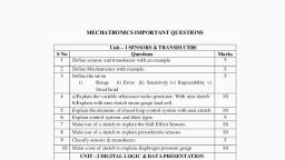
Mechatronics (15ME54T), , Selection of sensors, In selecting a sensor for a particular application there are a number of factors that need to be, considered., 1. The nature of the measurement required, e.g. the variable to be measured, its nominal, value, the range of values, the accuracy required, the required speed of measurement,, the reliability required, the environmental conditions under which the measurement is, to be made., 2. The nature of the output required from the sensor, this determining the signal, conditioning requirements in order to give suitable output signals from the, measurement., 3. Then possible sensors can be identified, taking into account such factors as their, range, accuracy, linearity, speed of response, reliability, maintainability, life, power, supply requirements, ruggedness, availability, cost., , REMEMBER QUESTIONS, 1., 2., 3., 4., 5., , Define Mechatronics?, Define system with example., Define sensors and transducers with an example., List the factors for selection of sensors., Define the terms: range and span, error, accuracy, sensitivity, hysteresis error, nonlinearity error, repeatability/reproducibility, stability, dead band/time, resolution,, output impedance., 6. List the performance features of sensors and transducers., , UNDERSTANDING QUESTIONS, 1., 2., 3., 4., 5., 6., , Explain the importance of mechatronics., Explain with a block diagram the measurement system., Explain control systems and their types., Classify the sensors and transducers., Explain sensors for displacement, position and proximity., Explain the working of light sensors., , Sandur Polytechnic, , Page 24, , Department of Mechanical Engineering
Page 25 :
Mechatronics (15ME54T), , APPLICATION QUESTIONS, 1. Make use of a sketch to explain the working of pneumatic sensors., 2. Build a line diagram and explain the function of each element of a measurement, system., 3. Make use of a sketch to explain the working of proximity switches., 4. Make use of a sketch to explain the working of optical encoder., 5. Make use of a sketch to explain the Hall Effect sensors., 6. Make use of a sketch to explain the working of tach generator., 7. Make use of a sketch to explain sketch bimetallic strip/thermostat., 8. Make use of a sketch to explain the working of a diaphragm pressure gauge., 9. Make use of a sketch to explain strain gauge load cell., 10. Make use of a sketch to explain piezoelectric sensor., 11. Make use of a sketch to explain turbine meter., 12. Make use of a sketch to explain float type liquid level meter., 13. Make use of a sketch to explain the working of LVDT., 14. Make use of a sketch to explain the bimetallic strip, , Sandur Polytechnic, , Page 25, , Department of Mechanical Engineering