Page 1 :
CONTENTS, CONTENTS, , + 0 ) 2 6 - 4, , Learning Objectives, ➣ Classification of AC Motors, ➣ Induction Motor: General, Principal, ➣ Construction, ➣ Phase-wound Rotor, ➣ Mathematical Proof, ➣ Relation between Torque and, Rotor Power Factor, ➣ Condition for Maximum Starting, Torque, ➣ Rotor E.M.F and Reactance, under Running Conditions, ➣ Condition for Maximum Torque, Under Running Conditions, ➣ Rotor Torque and Breakdown, Torque, ➣ Relation between Torque and, Slip, ➣ Full-load Torque and Maximum, Torque, ➣ Starting Torque and Maximum, Torque, ➣ Torque/Speed Characteristic, Under Load, ➣ Complete Torque/Speed Curve, of a Three-phase Machine, ➣ Power Stages in an Induction, Motor, ➣ Torque Developed by an, Induction Motor, ➣ Induction Motor Torque Equation, ➣ Variation in Rotor Current, ➣ Sector Induction Motor, ➣ Magnetic Levitation, ➣ Induction Motor as a Generalized Transformer, ➣ Power Balance Equation, ➣ Maximum Power Output, , CONTENTS, CONTENTS, , !", , INDUCTION, MOTOR, , high-speed magnetic levitation trains, Ç The, employ the principle of linear induction, motor
Page 2 :
1244, , Electrical Technology, , 34.1. Classification of A.C. Motors, With the almost universal adoption of a.c. system of distribution of electric energy for light and, power, the field of application of a.c. motors has widened considerably during recent years. As a, result, motor manufactures have tried, over the last few decades, to perfect various types of a.c., motors suitable for all classes of industrial drives and for both single and three-phase a.c. supply., This has given rise to bewildering multiplicity of types whose proper classification often offers, considerable difficulty. Different a.c. motors may, however, be classified and divided into various, groups from the following different points of view :, 1. AS REGARDS THEIR PRINCIPLE OF OPERA, TION, OPERATION, (A) Synchronous motors, (i) plain and (ii) super—, (B) Asynchronous motors, (a) Induction motors, (i) Squirrel cage single, double, (ii) Slip-ring (external resistance), (b) Commutator motors, single phase, (i) Series universal, conductively, (ii) Compensated, inductively, , {, , {, , (iii) shunt, (iv) repulsion, , {, , { simple, compensated, , Three phase high voltage asynchronous motors, , { straight, compensated, , (v) repulsion-start induction, (vi) repulsion induction, 2. AS REGARDS THE TYPE OF CURRENT, (i) single phase, (ii) three phase, 3. AS REGARDS THEIR SPEED, (i) constant speed, (ii) variable speed, (iii) adjustable speed, UCTURAL FEA, TURES, 4. AS REGARDS THEIR STR, STRUCTURAL, FEATURES, (i) open, (ii) enclosed, (iii) semi-enclosed, (iv) ventilated, (v) pipe-ventilated, (vi) riverted frame eye etc., , 34.2. Induction Motor : General Principle, , Fig. 34.1 Squirrel cage AC induction motor, opened to show the stator and rotor construction,, the shaft with bearings, and the cooling fan., , As a general rule, conversion of electrical power into, mechanical power takes place in the rotating part of, an electric motor. In d.c. motors, the electric power is, conducted directly to the armature (i.e. rotating part), through brushes and commutator (Art. 29.1). Hence,, in this sense, a d.c. motor can be called a conduction, motor. However, in a.c. motors, the rotor does not, receive electric power by conduction but by, induction in exactly the same way as the secondary, of a 2-winding transformer receives its power from
Page 3 :
Induction Motor, , 1245, , the primary. That is why such motors are known as induction motors. In fact, an induction motor can, be treated as a rotating transformer i.e. one in which primary winding is stationary but the secondary, is free to rotate (Art. 34.47)., Of all the a.c. motors, the polyphase induction motor is the one which is extensively used for various, kinds of industrial drives. It has the following main advantages and also some dis-advantages:, Advantages:, 1. It has very simple and extremely rugged, almost unbreakable construction (especially squirrelcage type)., 2. Its cost is low and it is very reliable., 3. It has sufficiently high efficiency. In normal running condition, no brushes are needed,, hence frictional losses are reduced. It has a reasonably good power factor., 4. It requires minimum of maintenance., 5. It starts up from rest and needs no extra starting motor and has not to be synchronised. Its, starting arrangement is simple especially for squirrel-cage type motor., Disadvantages:, 1. Its speed cannot be varied without sacrificing some of its efficiency., 2. Just like a d.c. shunt motor, its speed decreases with increase in load., 3. Its starting torque is somewhat inferior to that of a d.c. shunt motor., , 34.3. Construction, An induction motor consists essentially of two main parts :, (a) a stator and (b) a rotor., (a) Stator, The stator of an induction motor is, in principle, the same as that of a synchronous motor or generator., It is made up of a number of stampings, which are slotted to receive the windings [Fig.34.2 (a)]. The stator, carries a 3-phase winding [Fig.34.2 (b)] and is fed from a 3-phase supply. It is wound for a definite number, of poles*, the exact number of poles being determined by the requirements of speed. Greater the number of, poles, lesser the speed and vice versa. It will be shown in Art. 34.6 that the stator windings, when supplied, with 3-phase currents, produce a magnetic flux, which is of constant magnitude but which revolves (or, rotates) at synchronous speed (given by Ns = 120 f/P). This revolving magnetic flux induces an e.m.f. in the, rotor by mutual induction., , Fig. 34.2 (a) Unwound stator with semi-closed slots., Laminations are of high-quality low-loss silicon steel., (Courtesy : Gautam Electric Motors), , *, , Fig. 34.2 (b) Completely wound stator, for an induction motor., (Courtesy : Gautam Electric Motors), , The number of poles P, produced in the rotating field is P = 2n where n is the number of stator slots/pole/, phase.
Page 4 :
1246, , Electrical Technology, , (b) Rotor, (i) Squirrel-cage rotor : Motors employing this type of rotor are known as squirrel-cage induction, motors., (ii) Phase-wound or wound rotor : Motors employing this type of rotor are variously known as, ‘phase-wound’ motors or ‘wound’ motors or as ‘slip-ring’ motors., , 34.4. Squirrel-cage Rotor, Almost 90 per cent of induction motors are squirrel-cage type, because this type of rotor has the, simplest and most rugged construction imaginable and is almost indestructible. The rotor consists of, a cylindrical laminated core with parallel slots for carrying the rotor conductors which, it should be, , Fig. 34.3 (a) Squirrel-cage rotor with copper, bars and alloy brazed end-rings, (Courtesy : Gautam Electric Motors), , Fig. 34.3 (b) Rotor with shaft and brings, (Courtesy : Gautam Electric Motors), , noted clearly, are not wires but consist of heavy bars of copper, aluminium or alloys. One bar is placed, in each slot, rather the bars are inserted from the end when semi-closed slots are used. The rotor bars, are brazed or electrically welded or bolted to two heavy and stout short-circuiting end-rings, thus, giving us, what is so picturesquely called, a squirrel-case construction (Fig. 34.3)., It should be noted that the rotor bars are permanently short-circuited on themselves, hence it is, not possible to add any external resistance in series with the rotor circuit for starting purposes., The rotor slots are usually not quite parallel to the shaft but are purposely given a slight skew, (Fig. 34.4). This is useful in two ways :, (i) it helps to make the motor run quietly by reducing the magnetic hum and, (ii) it helps in reducing the locking tendency of the rotor i.e. the tendency of the rotor teeth to, remain under the stator teeth, due to direct magnetic attraction, Skewed, between the two.*, Rotor, Rotor Slots, In small motors, another method of, Shaft, End-Ring, construction is used. It consists of placing, Ball, the entire rotor core in a mould and casting, Bearings, all the bars and end-rings in one piece., The metal commonly used is an, aluminium alloy., Another form of rotor consists of a, solid cylinder of steel without any, conductors or slots at all. The motor, operation depends upon the production, of eddy currents in the steel rotor., Fig. 34.4, *, , Other results of skew which may or may not be desirable are (i) increase in the effective ratio of transformation, between stator and rotor (ii) increased rotor resistance due to increased length of rotor bars (iii) increased, impedance of the machine at a given slip and (iv) increased slip for a given torque.
Page 5 :
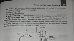
Induction Motor, , 1247, , 34.5. Phase-wound Rotor, This type of rotor is provided with 3-phase, double-layer, distributed winding consisting of coils, as used in alternators. The rotor is wound for as many poles as the number of stator poles and is, always wound 3-phase even when the stator is wound two-phase., The three phases are starred internally. The, other three winding terminals are brought out and, connected to three insulated slip-rings mounted, on the shaft with brushes resting on them [Fig., 34.5 (b)]. These three brushes are further, externally connected to a 3-phase star-connected, rheostat [Fig. 34.5 (c)]. This makes possible the, introduction of additional resistance in the rotor, circuit during the starting period for increasing, the starting torque of the motor, as shown in Fig., Fig. 34.5 (a), 34.6 (a) (Ex.34.7 and 34.10) and for changing its, speed-torque/current characteristics. When running under normal conditions, the slip-rings are, automatically short-circuited by means of a metal collar, which is pushed along the shaft and connects, all the rings together. Next, the brushes are automatically lifted from the slip-rings to reduce the, frictional losses and the wear and tear. Hence, it is seen that under normal running conditions, the, wound rotor is short-circuited on itself just like the squirrel-case rotor., Fig. 34.6 (b) shows the longitudinal section of a slip-ring motor, whose structural details are as under :, , Inlet, , Fig. 34.5 (b) Slip-ring motor with slip-rings, brushes and short-circuiting devices, (Courtesy : Kirloskar Electric Company), , Fig. 34.6 (a), , Contact, Studs, Fig. 34.5 (c), , Fig. 34.6 (b) Longitudinal section of a Jyoti, splash-proof slip-ring motor, (Courtesy : Jyoti Colour-Emag Ltd.)
Page 6 :
1248, , Electrical Technology, , 1. Frame. Made of close-grained alloy cast iron., 2. Stator and Rotor Core. Built from high-quality low-loss silicon steel laminations and flash-enamelled on both sides., 3. Stator and Rotor Windings. Have moisture proof tropical insulation embodying mica and high, quality varnishes. Are carefully spaced for most effective air circulation and are rigidly braced to, withstand centrifugal forces and any short-circuit stresses., 4. Air-gap. The stator rabbets and bore are machined carefully to ensure uniformity of air-gap., 5. Shafts and Bearings. Ball and roller bearings are used to suit heavy duty, toruble-free running, and for enhanced service life., 6. Fans. Light aluminium fans are used for adequate circulation of cooling air and are securely keyed, onto the rotor shaft., 7. Slip-rings and Slip-ring Enclosures. Slip-rings are made of high quality phosphor-bronze and, are of moulded construction., Fig. 34.6 (c) shows the disassembled view of an induction motor with squirrel-cage rotor., According to the labelled notation (a) represents stator (b) rotor (c) bearing shields (d) fan (e) ventilation grill and (f) terminal box., Similarly, Fig. 34.6 (d) shows the disassembled view of a slip-ring motor where (a) represents, stator (b) rotor (c) bearing shields (d) fan (e) ventilation grill (f) terminal box (g) slip-rings (h) brushes, and brush holders., e, e, , c, , h, , c, , e, , a, , e, , b, b, , d, , d, , d, Fig. 34.6 (c), , Fig. 34.6 (d), , 34.6. Production of Rotating Field, It will now be shown that when stationary, coils, wound for two or three phases, are supplied, by two or three-phase supply respectively, a, uniformly-rotating (or revolving) magnetic flux of, constant value is produced., Two-phase Supply, The principle of a 2-φ, 2-pole stator having, two identical windings, 90 space degrees apart,, is illustrated in Fig. 34.7., , Induction motor, , g
Page 7 :
1249, , Induction Motor, The flux due to the current flowing in each phase winding is assumed, sinusoidal and is represented in Fig. 34.9. The assumed positive directions, of fluxes are those shown in Fig. 34.8., Let Φ1 and Φ2 be the instantaneous values of the fluxes set up by, the two windings. The resultant flux Φr at any time is the vector sum of, these two fluxes (Φ1 and Φ2) at that time. We will consider conditions, at intervals of 1/8th of a time period i.e. at intervals corresponding to, angles of 0º, 45º, 90º, 135º and 180º. It will be shown that resultant, flux Φr is constant in magnitude i.e. equal to Φm-the maximum flux due, to either phase and is making one revolution/cycle. In other words, it, means that the resultant flux rotates synchronously., (a) When θ = 0º i.e. corresponding to point 0 in Fig. 34.9, Φ1, = 0, but Φ2 is maximum i.e. equal to Φm and negative., Hence, resultant flux Φr = Φm and, being negative, is shown, by a vector pointing downwards [Fig. 34.10 (i)]., , 2 Phase - 3 Wire, System, , S1, , F2, , S2, F1, Fig. 34.7, , (b) When θ = 45º i.e. corresponding to point 1 in Fig. 34.9. At this instant, Φ1 = Φm / 2 and is, positive; Φ2 = Φm / 2 but is still negative. Their resultant, as shown in Fig. 34.10 (ii), is Φr =, , [(φm / 2)2 + (φm / 2)2 ] = Φm although this resultant has shifted 45º clockwise., (c) When θ = 90º i.e. corresponding to point 2 in Fig. 34.9. Here Φ2 = 0, but Φ1 = Φm and is, positive. Hence, Φr = Φm and has further shifted by an angle of 45º from its position in (b) or by, 90º from its original position in (a)., (d) When θ = 135º i.e. corresponding to point 3 in Fig. 34.9. Here, Φ1 = Φm/ 2 and is positive, Φ2, = Φm / 2 and is also positive. The resultant Φr = Φm and has further shifted clockwise by, another 45º, as shown in Fig. 34.10 (iv)., , Fig. 34.8, , Fig. 34.9, , (e) When θ = 180º i.e. corresponding to point 4 in Fig. 34.9. Here, Φ1 = 0, Φ2 = Φm and is positive., Hence, Φr = Φm and has shifted clockwise by another 45º or has rotated through an angle of, 180º from its position at the beginning. This is shown in Fig. 34.10(v).
Page 8 :
1250, , Electrical Technology, , Fig. 34.10, , Hence, we conclude, 1. that the magnitude of the resultant flux is constant and is equal to Φm — the maximum, flux due to either phase., 2. that the resultant flux rotates at synchronous speed given by Ns = 120 f/P rpm., However, it should be clearly understood that in this revolving field, there is no actual revolution, of the flux. The flux due to each phase changes periodically, according to the changes in the phase, current, but the magnetic flux itself does not move around the stator. It is only the seat of the resultant, flux which keeps on shifting synchronously around the stator., Mathematical Proof, Let, Φ1 = Φm sin ωt and Φ2 = Φm sin (ωt − 90º), ∴, , Φr = Φ1 + Φ2, 2, , 2, , 2, , Φr2 = (Φm sin ωt)2 + [Φm sin (ωt − 90º)]2 = Φm2 (sin2 ωt + cos2 ωt) = Φm2, ∴, , Φ r = Φm, , It shows that the flux is of constant value and does not change with time., , 34.7. Three-phase Supply, It will now be shown that when three-phase windings displaced in space by 120º, are fed by threephase currents, displaced in time by 120º, they produce a resultant magnetic flux, which rotates in, space as if actual magnetic poles were being rotated mechanically., The principle of a 3-phase, two-pole stator having three identical windings placed 120 space, degrees apart is shown in Fig. 34.11. The flux (assumed sinusoidal) due to three-phase windings is, shown in Fig 34.12., The assumed positive directions of the fluxes are shown in Fig 34.13. Let the maximum value of, flux due to any one of the three phases be Φm. The resultant flux Φr, at any instant, is given by the, vector sum of the individual fluxes, Φ1, Φ2 and Φ3 due to three phases. We will consider values of Φr, at four instants 1/6th time-period apart corresponding to points marked 0, 1, 2 and 3 in Fig. 34.12.
Page 9 :
Induction Motor, (i) When θ = 0º i.e. corresponding to point, 0 in Fig. 34.12., Here Φ1 = 0, Φ 2 = −, , 3, Φ , Φ3 =, 2 m, , 3-�, , Supply, Neutral, , 3, Φ . The vector for Φ2 in Fig. 34.14 (i) is, 2 m, drawn in a direction opposite to the direction, assumed positive in Fig. 34.13., ∴, , 1251, , Φr = 2 × 3 Φm cos 60º = 3 ×, 2, 2, , 3, Φ = 3Φ, 2 m 2 m, , S1, F3, , F2, , S2, S3, , F1, , Fig. 34.11, , Fig. 34.12, , Fig. 34.13, , (ii) when θ = 60º i.e. corresponding to point 1 in Fig. 34.12., , 3, Φ, ...drawn parallel to OI of Fig. 34.13 as shown in Fig. 34.14 (ii), 2 m, 3, Φ2 = −, Φ, ...drawn in opposition to OII of Fig. 34.13., 2 m, Φ3 = 0, 3, 3, ∴, Φr = 2 ×, Φm × cos 30º = Φm, [Fig. 34.14 (ii)], 2, 2, 3, It is found that the resultant flux is again Φm but has rotated clockwise through an angle of 60º., 2, (iii) When θ = 120º i.e. corresponding to point 2 in Fig. 34.12., 3Φ, 3Φ, ,, Φ2 = 0, Φ3 = −, Here, Φ1 =, 2 m, 2 m, 3, It can be again proved that Φr = Φm., 2, So, the resultant is again of the same value, but has further rotated clockwise through an angle of, 60° [Fig. 34.14 (iii)]., Here Φ1 =
Page 10 :
1252, , Electrical Technology, o, , 60, _, F, , F, , 2, , F, , 3, , o, , 60, , 1, , _, , F, F, , F, r = 1.5, , r, , F, = 1.5, , (i) q = 0, , m, , (ii) q = 60, , o, , F, , r, , F, = 1.5, , 2, , m, o, , F, , F, , r, , F, = 1.5, , m, , m, , _, F, , 3, , _, F, (iii) q = 120, , 1, , 60, , F, , F, , 2, , 3, , o, , 60, , o, , (iv) q = 180, , o, , o, , Fig. 34.14, , (iv) When, , θ = 180° i.e. corresponding to point 3 in Fig. 34.12., Φ1 = 0, Φ2 =, , 3, 3, Φ , Φ3 = −, Φ, 2 m, 2 m, , 3, The resultant is Φm and has rotated clockwise through an additional angle 60º or through an, 2, angle of 180° from the start., Hence, we conclude that, 3, 1. the resultant flux is of constant value = Φm i.e. 1.5 times the maximum value of the flux, 2, due to any phase., 2. the resultant flux rotates around the stator at synchronous speed given by Ns = 120 f/P., Fig. 34.15 (a) shows the graph of the rotating flux in a simple way. As before, the positive, directions of the flux phasors have been shown separately in Fig. 34.15 (b). Arrows on these flux, phasors are reversed when each phase passes through zero and becomes negative.
Page 11 :
Induction Motor, , 1253, , Fig. 34.15, , As seen, positions of the resultant flux phasor have been shown at intervals of 60° only. The resultant, flux produces a field rotating in the clockwise direction., , 34.8. Mathematical Proof, Taking the direction of flux due to phase 1 as reference direction, we have, Φ1 = Φm (cos 0° + j sin 0°) sin ωt, Φ2 = Φm (cos 240° + j sin 240°) sin (ωt − 120°), Φ3 = Φm (cos 120° + j sin 120°) sin (ωt − 240°), Expanding and adding the above equations, we get, , 3, 3, Φ (sin ωt + j cos ωt) = Φm ∠ 90°− ωt, 2 m, 2, The resultant flux is of constant magnitude and does not change with time ‘t’., Φr =, , 34.9. Why Does the Rotor Rotate ?, The reason why the rotor of an induction motor is set into rotation is as follow:, When the 3-phase stator windings, are fed by a 3-phase, supply then, as seen from above, a magnetic flux of constant, magnitude, but rotating at synchronous speed, is set up., The flux passes through the air-gap, sweeps past the rotor, surface and so cuts the rotor conductors which, as yet, are, stationary. Due to the relative speed between the rotating, flux and the stationary conductors, an e.m.f. is induced in, the latter, according to Faraday’s laws of electro-magnetic, induction. The frequency of the induced e.m.f. is the same, as the supply frequency. Its magnitude is proportional to, Windings of induction electric motor, the relative velocity between the flux and the conductors, and its direction is given by Fleming’s Right-hand rule. Since, the rotor bars or conductors form a closed circuit, rotor current is produced whose direction, as given, by Lenz’s law, is such as to oppose the very cause producing it. In this case, the cause which, produces the rotor current is the relative velocity between the rotating flux of the stator and the, stationary rotor conductors. Hence, to reduce the relative speed, the rotor starts running in the same, direction as that of the flux and tries to catch up with the rotating flux., The setting up of the torque for rotating the rotor is explained below :
Page 12 :
1254, , Electrical Technology, , In Fig 34.16 (a) is shown the stator field which is assumed to be rotating clockwise. The relative, motion of the rotor with respect to the stator is anticlockwise. By applying Right-hand rule, the, direction of the induced e.m.f. in the rotor is found to be outwards. Hence, the direction of the flux due, to rotor current alone, is as shown in Fig. 34.16 (b). Now, by applying the Left-hand rule, or by the, effect of combined field [Fig. 34.16(c)] it is clear that the rotor conductors experience a force tending, to rotate them in clockwise direction. Hence, the rotor is set into rotation in the same direction as that, of the stator flux (or field)., , Fig. 34.16, , 34.10. Slip, In practice, the rotor never succeeds in ‘catching up’ with the stator field. If it really did so, then, there would be no relative speed between the two, hence no rotor e.m.f., no rotor current and so no, torque to maintain rotation. That is why the rotor runs at a speed which is always less than the speed, of the stator field. The difference in speeds depends upon the load on the motor.*, The difference between the synchronous speed Ns and the actual speed N of the rotor is known, as slip. Though it may be expressed in so many revolutions/second, yet it is usual to express it as a, percentage of the synchronous speed. Actually, the term ‘slip’ is descriptive of the way in which the, rotor ‘slips back’ from synchronism., Ns − N, × 100, % slip s =, Ns, Sometimes, Ns − N is called the slip speed., Obviously, rotor (or motor) speed is N = Ns (1 − s)., It may be kept in mind that revolving flux is rotating synchronously, relative to the stator (i.e., stationary space) but at slip speed relative to the rotor., , 34.11. Frequency of Rotor Current, When the rotor is stationary, the frequency of rotor current is the same as the supply frequency., But when the rotor starts revolving, then the frequency depends upon the relative speed or on slipspeed. Let at any slip-speed, the frequency of the rotor current be f ′. Then, 120 f ′, 120 f, Ns − N =, Also, Ns =, P, P, f ′ Ns − N, =s, Dividing one by the other, we get, f = N, ∴ f ′ = sf, s, As seen, rotor currents have a frequency of f ′ = sf and when flowing through the individual, *, , It may be noted that as the load is applied, the natural effect of the load or braking torque is to slow down the, motor. Hence, slip increases and with it increases the current and torque, till the driving torque of the motor, balances the retarding torque of the load. This fact determines the speed at which the motor runs on load.
Page 13 :
Induction Motor, , 1255, , phases of rotor winding, give rise to rotor magnetic fields. These individual rotor magnetic fields produce a, combined rotating magnetic field, whose speed relative to rotor is, 120 f ′ 120 sf, =, = sN S, P, P, However, the rotor itself is running at speed N with respect to space. Hence,, speed of rotor field in space = speed of rotor magnetic field relative to rotor + speed of rotor relative, to space, = sNs + N = sNs + Ns (1− s) = Ns, It means that no matter what the value of slip, rotor currents and stator currents each produce a, sinusoidally distributed magnetic field of constant magnitude and constant space speed of Ns. In, other words, both the rotor and stator fields rotate synchronously, which means that they are, stationary with respect to each other. These two synchronously rotating magnetic fields, in fact,, superimpose on each other and give rise to the actually existing rotating field, which corresponds to, the magnetising current of the stator winding., , =, , Example 34.1. A slip-ring induction motor runs at 290 r.p.m. at full load, when connected to, 50-Hz supply. Determine the number of poles and slip., (Utilisation of Electric Power AMIE Sec. B 1991), Solution. Since N is 290 rpm; Ns has to be somewhere near it, say 300 rpm. If Ns is assumed as 300, rpm, then 300 = 120 × 50/P. Hence, P = 20. ∴ s = (300 − 290)/300 = 3.33%, Example 34.2. The stator of a 3-φ induction motor has 3 slots per pole per phase. If supply, frequency is 50 Hz, calculate, (i) number of stator poles produced and total number of slots on the stator, (ii) speed of the rotating stator flux (or magnetic field)., Solution. (i), Total No. of slots, (ii), , P = 2n = 2 × 3 = 6 poles, = 3 slots/pole/phase × 6 poles × 3 phases = 54, N s = 120 f/P = 120 × 50/6 = 1000 r.p.m., , Example 34.3. A 4-pole, 3-phase induction motor operates from a supply whose frequency is 50, Hz. Calculate :, (i) the speed at which the magnetic field of the stator is rotating., (ii) the speed of the rotor when the slip is 0.04., (iii) the frequency of the rotor currents when the slip is 0.03., (iv) the frequency of the rotor currents at standstill., (Electrical Machinery II, Banglore Univ. 1991), Solution. (i) Stator field revolves at synchronous speed, given by, N s = 120 f/P = 120 × 50/4 = 1500 r.p.m., (ii) rotor (or motor) speed, N = Ns (1 − s) = 1500(1 − 0.04) = 1440 r.p.m., (iii) frequency of rotor current, f ′ = sf = 0.03 × 50 = 1.5 r.p.s = 90 r.p.m, (iv) Since at standstill,, s = 1, f ′ = sf = 1 × f = f = 50Hz, Example 34.4. A 3-φ induction motor is wound for 4 poles and is supplied from 50-Hz system., Calculate (i) the synchronous speed (ii) the rotor speed, when slip is 4% and (iii) rotor frequency, when rotor runs at 600 rpm., (Electrical Engineering-I, Pune Univ. 1991), Solution. (i), (ii) rotor speed,, , N s = 120 f/P = 120 × 50/4 = 1500 rpm, N = Ns (1 − s) = 1500 (1 − 0.04) = 1440 rpm
Page 14 :
1256, , Electrical Technology, , (iii) when rotor speed is 600 rpm, slip is, s = (Ns − N)/Ns = (1500 − 600)/1500 = 0.6, rotor current frequency,, f ′ = sf = 0.6 × 50 = 30 Hz, Example 34.5. A 12-pole, 3-phase alternator driven at a speed of 500 r.p.m. supplies power to, an 8-pole, 3-phase induction motor. If the slip of the motor, at full-load is 3%, calculate the full-load, speed of the motor., Solution. Let N = actual motor speed; Supply frequency, f = 12 × 500/120 = 50 Hz. Synchronous, speed Ns = 120 × 50/8 = 750 r.p.m., NS − N, 750 − N, × 100 ; 3 =, × 100, % slip s =, ∴ N = 727.5 r.p.m., 750, N, Note. Since slip is 3%, actual speed N is less than Ns by 3% of Ns i.e. by 3 × 750/100 = 22.5 r.p.m., , 34.12. Rela, tion Betw, een Tor, que and Rotor P, ower FFactor, actor, Relation, Between, orque, Po, In Art. 29.7, it has been shown that in the case of a d.c. motor, the torque Ta is proportional to the, product of armature current and flux per pole i.e. Ta ∝ φ Ia. Similarly, in the case of an induction motor,, the torque is also proportional to the product of flux per stator pole and the rotor current. However,, there is one more factor that has to be taken into account i.e. the power factor of the rotor., T = k φ I2 cos φ2, ∴ T ∝ φ I2 cos φ2 or, where, I2 = rotor current at standstill, φ2 = angle between rotor e.m.f. and, rotor current, k = a constant, Denoting rotor e.m.f. at standstill by E2, we have that E2 ∝ φ, ∴, T ∝ E2 I2 cos φ2, or, T = k1E2 I2 cos φ2, where k1 is another constant., The effect of rotor power factor on rotor torque is illustrated, in Fig. 34.17 and Fig. 34.18 for various values of φ2. From the, above expression for torque, it is clear that as φ2 increases (and, hence, cos φ2 decreases) the torque decreases and vice versa., In the discussion to follow, the stator flux distribution is, assumed sinusoidal. This revolving flux induces in each rotor, conductor or bar an e.m.f. whose value depends on the flux, density, in which the conductor is lying at the instant considered, Fig. 34.17, ( e = Blv volt). Hence, the induced e.m.f. in the rotor is also, sinusoidal., (i) Rotor Assumed Non-inductive (or φ2 = 0), In this case, the rotor current I2 is in phase with the e.m.f. E2 induced in the rotor (Fig. 34.17). The, instantaneous value of the torque acting on each rotor conductor is given by the product of, instantaneous value of the flux and the rotor current ( F ∝ BI2l ). Hence, torque curve is obtained by, plotting the products of flux φ (or flux density B) and I2. It is seen that the torque is always positive i.e., unidirectional., (ii) Rotor Assumed Inductive, This case is shown in Fig. 34.18. Here, I2 lags behind E2 by an angle φ2 = tan−1 X2/R2 where R2 =, rotor resistance/phase; X2 = rotor reactance/phase at standstill.
Page 15 :
Induction Motor, , 1257, , It is seen that for a portion, ‘ab’ of the pole pitch, the torque, is negative i.e. reversed. Hence,, the total torque which is the, difference of the forward and the, backward, torques,, is, considerably reduced. If φ2 =, 90°, then the total torque is zero, because in that case the, backward and the forward, torques become equal and, opposite., Fig. 34.18, , Fig. 34.19, , 34.13. Star, ting Tor, que, Starting, orque, The torque developed by the motor at the instant of starting is called starting torque. In some cases, it, is greater than the normal running torque, whereas in some other cases it is somewhat less., Let, E 2 = rotor e.m.f. per phase at standstill;, R2 = rotor resistance/phase, X 2 = rotor reactance/phase at standstill, ∴, , Z2 =, , Then,, , I2 =, , 2, 2, ( R2 + X 2 ) = rotor impedance/phase at standstill, , E2, =, Z2, , E2, 2, ( R2, , +, , 2, X2 ), , ; cos φ 2 =, , R2, =, Z2, , R2, 2, ( R2, , + X2 ), 2, , Standstill or starting torque Tst = k1 E2 I2 cos φ2, or, , Tst = k1E2 ., , E2, (R22, , +, , 2, X2 ), , ...Fig. 34.19, , ...Art. 34.12, , ×, , R2, (R22, , + X 22 ), , =, , k1E22 R2, R22 + X 22, , ...(i), , If supply voltage V is constant, then the flux Φ and hence, E2 both are constant., R, R, ∴, Tst = k2 2 2 2 = k2 22 where k2 is some other constant., R2 + X 2, Z2, 2, , Now,, , k1 =, , 3 , ∴, 3 . E2 R2, Tst =, 2πN s, 2πN s R 2 + X 2, 2, 2, , Where Ns → synchronous speed in rps., , 34.14. Star, ting Tor, que of a Squirr, el-cage Motor, Starting, orque, Squirrel-cage, The resistance of a squirrel-cage motor is fixed and small as compared to its reactance which is very, large especially at the start because at standstill, the frequency of the rotor currents equals the supply, frequency. Hence, the starting current I2 of the rotor, though very large in magnitude, lags by a very large, angle behind E2, with the result that the starting torque per ampere is very poor. It is roughly 1.5 times the, full-load torque, although the starting current is 5 to 7 times the full-load current. Hence, such motors are, not useful where the motor has to start against heavy loads., , 34.15. Star, ting Tor, que of a Slip-r, ing Motor, Starting, orque, Slip-ring, The starting torque of such a motor is increased by improving its power factor by adding external, resistance in the rotor circuit from the star-connected rheostat, the rheostat resistance being progres-
Page 16 :
1258, , Electrical Technology, , sively cut out as the motor gathers speed. Addition of external resistance, however, increases the rotor, impedance and so reduces the rotor current. At first, the effect of improved power factor predominates, the current-decreasing effect of impedance. Hence, starting torque is increased. But after a certain, point, the effect of increased impedance predominates the effect of improved power factor and so the, torque starts decreasing., , 34.16. Condition ffor, or Maxim, um Star, ting Tor, que, Maximum, Starting, orque, It can be proved that starting torque is maximum when rotor resistance equals rotor reactance., , dTst, R (2R2 ) , k 2 R2, 1, ∴, = k2 2, − 22, =0, Now, Tst =, 2, 2 2, 2, 2, dR2, R2 + X 2, R2 + X 2 (R2 + X 2 ) , or, , ∴, , R22 + X22 = 2R22, , R2 = X2., , 34.17. Ef, fect of Change in Supply Voltage on Star, ting Tor, que, Effect, Starting, orque, We have seen in Art. 34.13 that Tst =, 2, , ∴, , Tst =, , k3 V R2, R22 + X 22, , k1E22 R2, R22 + X 22, , . Now E2 ∝ supply voltage V, , 2, , =, , k3V R2, Z 22, , where k3 is yet another constant. Hence Tst ∝ V ., 2, , Clearly, the torque is very sensitive to any changes in the supply voltage. A change of 5 per cent in, supply voltage, for example, will produce a change of approximately 10% in the rotor torque. This fact is of, importance in star-delta and auto transformer starters (Art. 33-11)., Example 34.6. A 3-6 induction motor having a star-connected rotor has an induced e.m.f. of 80, volts between slip-rings at standstill on open-circuit. The rotor has a resistance and reactance per, phase of 1 Ω and 4 Ω respectively. Calculate current/phase and power factor when (a) slip-rings, are short-circuited (b) slip-rings are connected to a star-connected rheostat of 3 Ω per phase., (Electrical Technology, Bombay Univ. 1987, and similar example: Rajiv Gandhi Techn. Univ., Bhopal, Dec. 2000), Solution. Standstill e.m.f./rotor phase = 80 / 3 = 46.2 V, (a) Rotor impedance/phase, , =, , 2, 2, (1 + 4 ) = 4.12 Ω, , Rotor current/phase, = 46.2/4.12 = 11.2 A, Power factor, = cos φ = 1/4.12 = 0.243, As p.f. is low, the starting torque is also low., (b) Rotor resistance/phase, = 3+1=4Ω, 2, 2, Rotor impedance/phase = (4 + 4 ) = 5.66 Ω, ∴ Rotor current/phase, = 46.2/5.66 = 8.16 A; cos φ = 4/5.66 = 0.707., Hence, the starting torque is increased due to the improvement in the power factor. It will also be, noted that improvement in p.f. is much more than the decrease in current due to increased impedance., , Example 34.7. A 3-phase, 400-V, star-connected induction motor has a star-connected rotor, with a stator to rotor turn ratio of 6.5. The rotor resistance and standstill reactance per phase are, 0.05 Ω and 0.25 Ω respectively. What should be the value of external resistance per phase to be, inserted in the rotor circuit to obtain maximum torque at starting and what will be rotor starting, current with this resistance?, 1 because transformation ratio K is defined as, Solution. Here, K =, 6.5
Page 17 :
Induction Motor, =, , 1259, , rotor turns/phase, stator turns/phase, , 400 × 1 = 35.5 volt, 3 6.5, It has been shown in Art. 34.16 that starting torque is maximum when R2 = X2 i.e. when, R2 = 0.25 Ω in the present case, ∴ External resistance/phase required = 0.25 − 0.05 = 0.2 Ω, , Standstill rotor e.m.f./phase, E2 =, , 2, 2, Rotor impedance/phase = (0.25 + 0.25 ) = 0.3535 Ω, Rotor current/phase, I2 = 35.5/0.3535 = 100 A (approx), , Example 34.8. A 1100-V, 50-Hz delta-connected induction motor has a star-connected slip-ring, rotor with a phase transformation ratio of 3.8. The rotor resistance and standstill leakage reactance are 0.012 ohm and 0.25 ohm per phase respectively. Neglecting stator impedance and, magnetising current determine., (i) the rotor current at start with slip-rings shorted, (ii) the rotor power factor at start with slip-rings shorted, (iii) the rotor current at 4% slip with slip-rings shorted, (iv) the rotor power factor at 4% slip with slip-rings shorted, (v) the external rotor resistance per phase required to obtain a starting current of 100 A in the, stator supply lines., (Elect. Machines AMIE Sec. B 1992), Solution. It should be noted that in a ∆/Y connection, primary phase voltage is the same as the, line voltage. The rotor phase voltage can be found by using the phase transformation ratio of 3.8 i.e., K = 1/3.8., Rotor phase voltage at standstill = 1100 × 1/3.8 = 289.5V, (i) Rotor impedence/phase, , =, , 0.012 + 0.25 = 0.2503 Ω, 2, , 2, , Rotor phase current at start = 289.5/0.2503 = 1157 A, (ii), p.f. = R2/Z2 = 0.012/0.2503 = 0.048 lag, (iii) at 4% slip,, X r = sX2 = 0.04 × 0.25 = 0.01 Ω, ∴, (iv), (v), , Zr =, , 0.0122 + 0.012 = 0.0156 Ω, , E r = sE2 = 0.04 × 289.5 = 11.58 V; I2 = 11.58/0.0156 = 742.3 A, p.f. = 0.012/0.0156 = 0.77, I2 = I1/K = 100 × 3.8 = 380 A; E2 at standstill = 289.5 V, Z2 = 289.5/380 = 0.7618 Ω; R2 =, , Z 22 − X 22 = 0.76182 − 0.252 = 0.7196 Ω, , ∴ External resistance reqd./phase = 0.7196 − 0.012 = 0.707 Ω, Example 34.9. A 150-kw, 3000-V, 50-Hz, 6-pole star-connected induction motor has a starconnected slip-ring rotor with a transformation ratio of 3.6 (stator/rotor). The rotor resistance is, 0.1Ω/phase and its per phase leakage reactance is 3.61 mH. The stator impedance may be neglected., Find the starting current and starting torque on rated voltage with short-circuited slip rings., (Elect. Machines, A.M.I.E. Sec. B, 1989), −3, Solution., X2 = 2π × 50 × 5.61 × 10 = 1.13 Ω, K = 1/3.6, R2′= R2/K = (3.6) × 0.1 = 1.3 Ω, 2, , 2, , −3, , X2 = 2π × 50 × 3.61 × 10 = 1.13 Ω ; X2′ = (3.6) × 1.13 = 14.7Ω, 2
Page 18 :
1260, , Electrical Technology, Ist =, , Now,, , 3000 / 3, V, ., = 117.4 A, 2, 2, 2, ( R2 ′) + ( X 2 ′), (1.3) + (14.7), 2, , Ns = 120 × 50/6 = 1000 rpm = (50/3) rps, V R2 ′, (3000 / 3) 2 × 1.3, 3, 3, ., =, ×, = 513 N-m, 2πN s ( R ′) 2 + ( X ′) 2 2π (50 / 3), (1.32 + 14.7 2 ), 2, 2, 2, , Tst =, , Tutor, ial Pr, oblem No. 34.1, utorial, Problem, 1., , In the case of an 8-pole induction motor, the supply frequency was 50-Hz and the shaft speed was, 735 r.p.m. What were the magnitudes of the following:, (Nagpur Univ., Summer 2000), (i), (iii), , synchronous speed, , (ii), , speed of slip, , per unit slip, , (iv), , percentage slip, [750 r.p.m. ; 15 r.p.m.; 0.02 ; 2%], , 2., , A 6-pole, 50-Hz squirrel-cage induction motor runs on load at a shaft speed of 970 r.p.m., Calculate:(i) the percentage slip, [3% ; 1.5 Hz], (ii) the frequency of induced current in the rotor., , 3., , An 8-pole alternator runs at 750. r.p.m. and supplies power to a 6-pole induction motor which has, at full-load a slip of 3%. Find the full-load speed of the induction motor and the frequency of its, rotor e.m.f., [970 r.p.m. ; 1.5 Hz], , 4., , A 3-phase, 50-Hz induction motor with its rotor star-connected gives 500 V (r.m.s.) at standstill, between the slip-rings on open-circuit. Calculate the current and power factor at standstill when the, rotor winding is joined to a star-connected external circuit, each phase of which has a resistance of, 10 Ω and an inductance of 0.04 H. The resistance per phase of the rotor winding is 0.2 Ω and its, inductance is 0.04 H., Also, calculate the current and power factor when the slip-rings are short-circuited and the motor is, running with a slip of 5 per cent. Assume the flux to remain constant., [10.67 A; 0.376; 21.95 A; 0.303], , 5., , Obtain an expression for the condition of maximum torque of an induction motor. Sketch the torqueslip curves for several values of rotor circuit resistance and indicate the condition for maximum, torque to be obtained at starting., If the motor has a rotor resistance of 0.02 Ω and a standstill reactance of 0.1 Ω, what must be the, value of the total resistance of a starter for the rotor circuit for maximum torque to be exerted at, starting ?, [0.08 Ω] (City and Guilds, London), , 6., , The rotor of a 6-pole, 50-Hz induction motor is rotated by some means at 1000 r.p.m. Compute, (i) rotor voltage (ii) rotor frequency (iii) rotor slip and (iv) torque developed. Can the rotor rotate at, this speed by itself ?, [(i) 0 (ii) 0 (iii) 0 (iv) 0; No] (Elect. Engg. Grad I.E.T.E. June 1985), , 7., , The rotor resistances per phase of a 4-pole, 50-Hz, 3-phase induction motor are 0.024 ohm and 0.12, ohm respectively. Find the speed at maximum torque. Also find the value of the additional rotor, resistance per phase required to develop 80% of maximum torque at starting., , 8., , The resistance and reactance per phase of the rotor of a 3-phase induction motor are 0.6 ohm and, 5 ohms respectively. The induction motor has a star-connected rotor and when the stator is, connected to a supply of normal voltage, the induced e.m.f. between the slip rings at standstill is 80, V. Calculate the current in each phase and the power factor at starting when (i) the slip-rings are, shorted, (ii) slip-rings are connected to a star-connected resistance of 4 ohm per phase., , [1200 r.p.m. 0.036 Ω] (Elect. Machines, A.M.I.E. Sec. B, 1990), , [(i) 9.17 amp, 0.1194 lag (ii) 6.8 amp, 0.6765 lag][Rajiv Gandhi Technical University, Bhopal, 2000]
Page 19 :
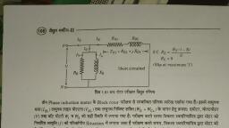
Induction Motor, , 1261, , 34.18. Rotor E.M.F, E.M.F.. and Reactance Under Running Conditions, Let, , E 2 = standstill rotor induced e.m.f./phase, X 2 = standstill rotor reactance/phase, f2 = rotor current frequency at standstill, When rotor is stationary i.e. s = 1, the frequency of rotor e.m.f. is the same as that of the stator supply, frequency. The value of e.m.f. induced in the rotor at standstill is maximum because the relative speed, between the rotor and the revolving stator flux is maximum. In fact, the motor is equivalent to a 3-phase, transformer with a short-circuited rotating secondary., When rotor starts running, the relative speed between it and the rotating stator flux is decreased., Hence, the rotor induced e.m.f. which is directly proportional to this relative speed, is also decreased, (and may disappear altogether if rotor speed were to become equal to the speed of stator flux). Hence,, for a slip s, the rotor induced e.m.f. will be s times the induced e.m.f. at standstill., Therefore, under running conditions Er = sE2, The frequency of the induced e.m.f. will likewise become fr = sf2, Due to decrease in frequency of the rotor e.m.f., the rotor reactance will also decrease., ∴, X r = sX2, where Er and Xr are rotor e.m.f. and reactance under running conditions., , 34.19. Tor, que Under Running Conditions, orque, T ∝ ErIr cos φ2 or T ∝ φ Ir cos φ2, Er = rotor e.m.f./phase under running conditions, Ir = rotor current/phase under running conditions, Now, Er = sE2, E, sE2, ∴, Ir = r =, 2, 2, Zr, [ R + ( sX ) ], , (3 Er ∝ φ), , where, , 2, , AlsoT, , 2, , R2, , cos φ2 =, ∴, , —Fig. 34.20, 2, 2, [ R2 + (sX 2 ) ], s Φ E2 R2, k Φ . s . E2 R2, T ∝ 2, = 2, 2, R2 + ( sX 2 ), R2 + (sX 2 ) 2, =, , C, , k1 . sE22 R2, R22 + (sX 2 )2, , (3 E2 ∝ φ), , Zr, f, A, , SX2, , 2, , R2, , B, , Fig. 34.20, , where k1 is another constant. Its value can be proved to be equal to 3/2 πNs (Art. 34.38). Hence, in that, case, expression for torque becomes, 2, 2, sE2 R2, sE R, 3, = 3 . 222, T = 2πN . 2, 2, 2πN S, Zr, S R2 + (sX 2 ), At standstill when s = 1, obviously, Tst, , 2, 2, k1E2 R2 , 3 . E2 R2 , or, =, , , =, 2, 2, 2πN S R 2 + X 2 , R2 + X 2 , 2, 2 , , the same as in Art. 34.13., , Example 34.10. The star connected rotor of an induction motor has a standstill impedance of, (0.4 + j4) ohm per phase and the rheostat impedance per phase is (6 + J2) ohm., The motor has an induced emf of 80 V between slip-rings at standstill when connected to its, normal supply voltage. Find
Page 20 :
1262, , Electrical Technology, , (i) rotor current at standstill with the rheostat is in the circuit., (ii) when the slip-rings are short-circuited and motor is running with a slip of 3%., (Elect.Engg. I, Nagpur Univ. 1993), Solution. (1) Standstill Conditions, Voltage/rotor phase, starter impedance/phase, Rotor current/phase, (2) Running Conditions., Rotor voltage/phase,, Rotor reactance/phase,, Rotor impedance/phase,, Rotor current/phase, , = 80 / 3 = 46.2. V; rotor and, = (6.4 + j6) = 8.77 ∠ 43.15°, = 46.2/8.77 = 5.27 A (p.f. = cos 43.15° = 0.729), Here, starter impedance is cut out., Er = sE2 = 0.03 × 46.2 = 1.386 V, Xr = 0.03 × 4 = 0.12 Ω, Zr = 0.4 + j0.12 = 0.4176 ∠16.7°, = 1.386/0.4176 = 3.32 A (p.f. = cos 16.7° = 0.96), , Note. It has been assumed that flux across the air -gap remains constant, , 34.20. Condition ffor, or Maxim, um Tor, que Under Running Conditions, Maximum, orque, The torque of a rotor under running conditions is, T =, , k ΦsE2 R2, , sE 22 R2, , = k1, , ...(i), 2, 2, 2, 2, R2 + (sX 2 ), R2 + (sX 2 ), The condition for maximum torque may be obtained by differentiating the above expression, 1, with respect to slip s and then putting it equal to zero. However, it is simpler to put Y = and then, T, differentiate it., 2, 2, − R2, R2, sX 22, X 22, R + ( sX 2 ), ; dY =, =, ∴, Y= 2, +, +, =0, k Φ sE2 k Φ E2 R2 ds k Φ s 2 E, k ΦE2 R2, k Φ sE2 R2, 2, , ∴, , R2, k Φ s E2, 2, , =, , X 22, k Φ E2 R2, , 2, , 2, , 2, , or R2 = s X2 or R2 = sX2, , Hence, torque under running condition is maximum at that value of the slip s which makes rotor, reactance per phase equal to rotor resistance per phase. This slip is sometimes written as sb and the, maximum torque as Tb., Slip corresponding to maximum torque is s = R2/X2, Putting R2 = sX2 in the above equation for the torque, we get, 2, k Φ s E2 X 2 k Φ sE2 R2 , k Φ E2 k Φ sE2 , or, Tmax =, ...(ii), or, or Tmax =, 2, 2, 2, , , 2 X 2 , 2 R2 , 2 s X2 , 2R2, , Substituting value of s = R2/X2 in the other equation given in (i) above, we get, (R / X ) . E22 . R2, E22, =, k, Tmax = k1 2 2 2, 1, 2, 2, 2 X2, R + (R / X ) . X, 2, , 2, , 2, , 2, , 2, , Since,, , k 1 = 3/2π Ns, we have Tmax =, , 3 . E2, N-m, 2πN s 2 X 2, , From the above, it is found, 1. that the maximum torque is independent of rotor resistance as such., 2. however, the speed or slip at which maximum torque occurs is determined by the rotor
Page 21 :
Induction Motor, , 3., 4., 5., , 1263, , resistance. As seen from above, torque becomes maximum when rotor reactance equals its, resistance. Hence, by varying rotor resistance (possible only with slip-ring motors) maximum torque can be made to occur at any desired slip (or motor speed)., maximum torque varies inversely as standstill reactance. Hence, it should be kept as small, as possible., maximum torque varies directly as the square of the applied voltage., for obtaining maximum torque at starting (s =1), rotor resistance must be equal to rotor, reactance., , Example 34.11. A 3-phase, slip-ring, induction motor with star-connected rotor has an, induced e.m.f. of 120 volts between slip-rings at standstill with normal voltage applied to the stator., The rotor winding has a resistance per phase of 0.3 ohm and standstill leakage reactance per phase, of 1.5 ohm., Calculate (i) rotor current/phase when running short-circuited with 4 percent slip and (ii) the, slip and rotor current per phase when the rotor is developing maximum torque., (Elect. Engg.-II, Pune Univ. 1989), Solution. (i) induced e.m.f./rotor phase, Er = sE2 = 0.04 × (120/ 3 ) = 2.77V, rotor reactance/phase,, X r = sX2 = 0.04 × 1.5 = 0.06 Ω, rotor impedance/phase, , =, , 0.3 + 0.06 = 0.306 Ω, 2, , 2, , rotor current/phase, = 2.77/0.306 = 9A, (ii) For developing maximum torque,, R2 = sX2 or s = R2/X2 = 0.3/1.5 = 0.2, X r = 0.2 × 1.5 = 0.3 Ω, Zr =, ∴ Rotor current/phase, , 0.3 + 0.3 = 0.42 Ω, 2, , 2, , E r = sE2= 0.2 × (120/ 3 ) = 13.86 V, = 13.86/0.42 = 33 A, , 34.21. Rotor Tor, que and Br, eakdo, wn Tor, que, orque, Breakdo, eakdown, orque, The rotor torque at any slip s can be expressed in terms of the maximum (or breakdown) torque Tb, by the following equation, , 2, , T = Tb , (sb / s) + (s / sb ) where sb is the breakdown or pull-out slip., Example 34.12. Calculate the torque exerted by an 8-pole, 50-Hz, 3-phase induction motor, operating with a 4 per cent slip which develops a maximum torque of 150 kg-m at a speed of, 660 r.p.m. The resistance per phase of the rotor is 0.5 Ω. (Elect. Machines, A.M.I.E. Sec. B, 1989), Solution., Speed at maximum torque, , N s = 120 × 50/8 = 750 r.p.m., = 660 r.p.m. Corresponding slip sb =, , 750 − 660, = 0.12, 750, , For maximum torque,, R2 = sb X2, ∴, X2 = R2/sb = 0.5/0.12 = 4.167 Ω, As seen from Eq. (ii) of Art. 34.20,, s, Tmax = k Φ E2 . b = k Φ E2 . 0.12 = 0.12 k Φ E2, 2R2, 2 × 0.5, When slip is 4 per cent, As seen from Eq. (i) of Art. 34.20, , ...(i)
Page 22 :
1264, , Electrical Technology, T = k Φ E2, , ∴, , T, Tmax, , sR2, , + ( sX 2 ), 0.02, = T =, 150 0.2778 × 0.12, R22, , 2, , = k Φ E2, , 0.02 k Φ E2, 0.04 × 0.5, =, 2, 0.2778, 0.5 + (0.04 × 4.167), 2, , ∴ T = 90 kg-m, , Alternative Solution, T b = 150 kg.m; sb = 0.12, s = 4% = 0.04, T = ?, , , 2, T = Tb , , (sb / s) + (s / sb ) , , ...Art 34.21, , , , 2, = 150 , = 90 kg-m, (0.12 / 0.04) + (0.04 / 0.12) , , 34.22. Rela, tion Betw, een Tor, que and Slip, Relation, Between, orque, A family of torque/slip curves is shown in Fig. 34.21 for a range of s = 0 to s = 1 with R2 as the, parameter. We have seen above in Art., 34.19 that, Max. Torque, k Φ sE2 R2, T =, 2, 2, R2 + ( sX 2 ), , 6R, , Torque, , It is clear that when s = 0, T = 0, hence, the curve starts from point O., At normal speeds, close to synchronism, the term (s X2) is small and hence, negligible w.r.t. R2., s, ∴, T ∝, R2, , 4R, R, , or, T ∝ s if R2 is constant., Hence, for low values of slip, the, torque/slip curve is approximately a, 0, 0.2, 0.4, 0.6, 0.8, 1.0, straight line. As slip increases (for, Slip, increasing load on the motor), the torque, 1.0, 0.8, 0.6, 0.4, 0.2, 0, also increases and becomes maximum, Speed % of NS, when s = R2/X2. This torque is known as, ‘pull-out’ or ‘breakdown’ torque Tb or, Fig. 34.21, stalling torque. As the slip further, increases (i.e. motor speed falls) with further increase in motor load, then R2 becomes negligible as, compared to (sX2.). Therefore, for large values of slip, s ∝1, T ∝, (sX 2 ) 2 s, Hence, the torque/slip curve is a rectangular hyperbola. So, we see that beyond the point of, maximum torque, any further increase in motor load results in decrease of torque developed by the, motor. The result is that the motor slows down and eventually stops. The circuit-breakers will be, tripped open if the circuit has been so protected. In fact, the stable operation of the motor lies between, the values of s = 0 and that corresponding to maximum torque. The operating range is shown shaded, in Fig. 34.21., It is seen that although maximum torque does not depend on R2, yet the exact location of Tmax is, dependent on it. Greater the R2, greater is the value of slip at which the maximum torque occurs.
Page 23 :
1265, , Induction Motor, , 34.23. Ef, fect of Change in Supply Voltage on Tor, que and Speed, Effect, orque, k Φ sE2 R2, , As seen from Art. 34.19, T =, , R22 + ( sX 2 ) 2, , As, E2 ∝ φ ∝ V where V is supply voltage, ∴ T ∝ sV, Obviously, torque at any speed is proportional to the square of the applied voltage. If stator, voltage decreases by 10%, the torque decreases by 20%. Changes in supply voltage not only affect, the starting torque Tst but torque under running conditions also. If V decreases, then T also decreases., Hence, for maintaining the same torque, slip increases i.e. speed falls., 2, , 2, , Let V change to V ′, s to s′ and T to T′; then T = sV, T ′ s′ V ′ 2, , 34.24. Ef, fect of Changes in supply Fr, equenc, y on Tor, que and Speed, Effect, Frequenc, equency, orque, Hardly any important changes in frequency take place on a large distribution system except, during a major disturbance. However, large frequency changes often take place on isolated, lowpower systems in which electric energy is generated by means of diesel engines or gas turbines., Examples of such systems are : emergency supply in a hospital and the electrical system on a ship etc., The major effect of change in supply frequency is on motor speed. If frequency drops by 10%,, then motor speed also drops by 10%. Machine tools and other motor-driven equipment meant for 50, Hz causes problem when connected to 60-Hz supply. Everything runs (60 − 50) × 100/50 = 20% faster, than normal and this may not be acceptable in all applications. In that case, we have to use either gears, to reduce motor speed or an expensive 50-Hz source., A 50-Hz motor operates well on a 60-Hz line provided its terminal voltage is raised to, 60/50 = 6/5 (i.e. 120%) of the name-plate rating. In that case, the new breakdown torque becomes equal, to the original breakdown torque and the starting torque is only slightly reduced. However, power, factor, efficiency and temperature rise remain satisfactory., Similarly, a 60-Hz motor can operate satisfactorily on 50-Hz supply provided its terminal voltage, is reduced to 5/6 (i.e. 80%) of its name-plate rating., , 34.25. Full-load Tor, que and Maxim, um Tor, que, orque, Maximum, orque, Let sf be the slip corresponding to full-load torque, then, Tf ∝, , Tf, , ∴, , Tmax, , =, , s f R2, 2, R2, , + (s f X 2 ), , and Tmax ∝, , 2, , 1, 2 × X2, , 2s f R2 X 2, 2, R2, , + (s f X 2 ), , 2, , Dividing both the numerator and the denominator by X22, we get, , Tf, Tmax, , =, , 2s f . R2 / X 2, ( R2 / X 2 ) +, 2, , 2, sf, , =, , 2as f, a + sf, 2, , 2, , where a = R2/X2 = resistance/standstill reactance*, *, , In fact a = sm —slip corresponding to maximum torque. In that case, the relation becomes, , Tf, Tmax, , 2, , =, , 2sm s f, , 2, + s 2f, sm, , — where sf = full-load slip., , ...Art 34.20
Page 24 :
1266, , Electrical Technology, , In general,, , 2 as, operating torque at any slip s, = a2 + s 2, maximum torque, f, , 34.26. Star, ting Tor, que and Maxim, um Tor, que, Starting, orque, Maximum, orque, Tst ∝, Tmax ∝, , Tst, Tmax, , ∴, where, , =, , R2, R22, , ...Art 34.13, , + X 22, , 1, 2 X2, 2 R2 X 2, R22, , +, , ...Art. 34.20, =, , X 22, , 2 R2 / X 2, 1 + ( R2 / X 2 ) 2, , =, , 2a, 1 + a2, , R2, rotor resistance, =, per phase*, X 2 stand still reactance, , a =, , Example. 34.13(a). A 3-φ induction motor is driving full-load torque which is independent of, speed. If line voltage drops to 90% of the rated value, find the increase in motor copper losses., 2, , 2, , Solution. As seen from Art. 34.23, when T remains constant, s1 V1 = s2 V2, , s2, s1, , ∴, , ( ) = 1.23, , 2, , V , = 1 = 1, 0.9, V2 , , I 2′ s2V2, =, = 1.2 × 0.9 = 1.107, I 2 s1V1, , Again from Art. 34-19, I2 ∝ sV ∴, , Now, Cu losses are nearly proportional to I2, ∴, , Cu loss in the 2nd case, Cu loss in the 1st case =, , 2, , ( I 2′ )2, , 2, , 2, , = 1.107 = 1.23, , I 22, , Thus a reduction of 10% in line voltage causes about 23% increase in Cu losses., Example. 34.13 (b). A 230-V, 6-pole, 3-φ, 50-Hz, 15-kW induction motor drives a constant torque, load at rated frequency, rated voltage and rated kW output and has a speed of 980 rpm and an, efficiency of 93%. Calculate (i) the new operating speed if there is a 10% drop in voltage and 5%, drop in frequency and (ii) the new output power. Assume all losses to remain constant., Solution. (i) V2 = 0.9 × 230 = 207 V; f2 = 0.95 × 50 = 47.5 Hz; Ns1 = 120 × 50/6 = 1000 rpm; Ns2 = 120, × 47.5/6 = 950 rpm; s1 = (1000 − 980)/1000 = 0.02, 2, Since the load torque remains constant, the product (sV /f ) remains constant., 2, , 2, s2V2, V , ∴ s1V1 /f1 =, or s2 = s1 1 . f2/f1 = 0.02 (230/230 × 0.9)2 × 47.5/50 = 0.2234, f2, V2 , ∴, N2 = Ns2 (1 − s2) = 950 (1 − 0.0234) = 928 rpm, , 2, , (ii) P ∝ TN . Since torque remains constant, P ∝ N, ∴ P1 ∝ N1; P2 ∝ N2 ; or P2 = P1 × N2/N1 = 15 × 928/980 = 14.2 kW, , *, , Similarly, the relation becomes, , Tf, Tmax, , =, , 2sm, 2, , 1 + sm
Page 25 :
Induction Motor, , 1267, , Example 34.14 (a). A 3-phase, 400/200-V, Y-Y connected wound-rotor induction motor has, 0.06Ω rotor resistance and 0.3 Ω standstill reactance per phase. Find the additional resistance, required in the rotor circuit to make the starting torque equal to the maximum torque of the motor., (Electrical Technology, Bombay Univ. 1990), , Tst, Tmax, , 2a ;, Since Tst = Tmax, 1 + a2, R +r, 2a, ∴, 1 =, or a = 1 Now, a = 2, 2, X2, 1+ a, where, r = external resistance per phase added to the rotor circuit, 0.06 + r, ∴, 1 =, ∴ r = 0.3 − 0.06 = 0.24 Ω, 0.3, Example 34.14 (b). 3-phase, 50-Hz, 8-pole, induction motor has full-load slip of 2%. The rotorresistance and stand still rotor-reactance per phase are 0.001 ohm and 0.005 ohm respectively., Find the ratio of the maximum to full-load torque and the speed at which the maximum torque, occurs., (Amravati University, 1999), Solution. Synchronous speed, Ns = 120 × 50/8 = 750 rpm, Slip at maximum torque, smT = r2/x2, r2 0.001, Thus, let a, = x = 0.005 = 0.2, 2, Corresponding speed, = (1 − 0.2) × 750 = 600 rpm, 2, 2 smT s fL, Full − load torque, T fL, 2 × 0.2 × 0.022 1.6 × 10⁻⁴, =, =, =, ∴, 2, 2, Maximum torque, 0.0404, Tmax, smT + s fL, 0.202 + 0.022, Solution., , ∴, , =, , Tmax, T f = 252.5, −3, , = 3.96 × 10−, , Example 34.14 (c). A 12-pole, 3-phase, 600-V, 50-Hz, star-connected, induction motor has, rotor-resistance and stand-still reactance of 0.03 and 0.5 ohm per phase respectively. Calculate:, (a) Speed of maximum torque. (b) ratio of full-load torque to maximum torque, if the full-load, speed is 495 rpm., (Nagpur University, April 1999), Solution. For a 12-pole, 50 Hz motor,, Synchronous speed = 120 × 50 / 12 = 500 rpm, For r = 0.03 and x = 0.5 ohm, the slip for maximum torque is related as :, SmT = a = r/x = 0.03/0.5 = 0.06, (a) Corresponding speed, = 500 (1 − smT) = 470 rpm, (b) Full-load speed, = 495 rpm, slip s = 0.01, at full load., 2 as, 2 × 0.06 × 0.01, Full-load torque, = 2, =, = 0.324, 2, Maximum torque, 0.062 + 0.012, a +s, Example 34.15. A 746-kW, 3-phase, 50-Hz, 16-pole induction motor has a rotor impedance of, (0.02 + j 0.15) W at standstill. Full-load torque is obtained at 360 rpm. Calculate (i) the ratio of, maximum to full-load torque (ii) the speed of maximum torque and (iii) the rotor resistance to be, added to get maximum starting torque., (Elect. Machines, Nagpur Univ. 1993), Solution. Let us first find out the value of full-load slip sf, N s = 120 × 50/16 = 375 rpm.; F.L. Speed = 360 rpm., sf = (375 − 360)/375 = 0.04; a = R2/X2 = 0.02/0.15 = 2/15
Page 26 :
1268, , Electrical Technology, , Tf, Tmax, , (i), , =, , 2as f, a +, 2, , 2, sf, , =, , 2 × (2 /15) × 0.04, (2 /15) + (0.04), 2, , 2, , = 0.55 or, , Tmax, = 1 = 1.818, 0.55, Tf, , (ii) At maximum torque,, , a = sm = R2/X2 = 0.02/0.15 = 2/15, N = Ns (1 − s) = 375 (1 − 2/15) = 325 r.p.m., Ω, (iii) For maximum starting torque, R2 = X2. Hence, total rotor resistance per phase = 0.15Ω, ∴ external resistance required/phase = 0.15 − 0.02 = 0.13 Ω, Example 34.16. The rotor resistance and reactance per phase of a 4-pole, 50-Hz, 3-phase, induction motor are 0.025 ohm and 0.12 ohm respectively. Make simplifying assumptions, state, them and :, (i) find speed at maximum torque, (ii) find value of additional rotor resistance per phase required to give three-fourth of maximum, torque at starting. Draw the equivalent circuit of a single-phase induction motor., (Elect. Machines, Nagpur Univ. 1993), Solution. (i) At maximum torque, s = R2/X2 = 0.025/0.12 = 0.208., ∴ N = 1500 (1 − 0.208) = 1188 rpm, N s = 120 × 50/4=1500 rpm, (ii) It is given that, , Tst = 0.75 Tmax Now,, , Tst, = 2a = 3, Tmax 1 + a 2 4, , 8 ± 64 − 36, = 0.45 Ω *, 6, r = additional rotor resistance reqd., then, R +r, 0.025 + r, or 0.45 =, Ω, a = 2, ∴ r = 0.029Ω, 0.12, R2, , ∴ 3a − 8a + 3 = 0 ;, 2, , a =, , Let,, , Example. 34.17. A 50-Hz, 8-pole induction motor has F.L. slip of 4%. The rotor resistance/phase, = 0.01 ohm and standstill reactance/phase = 0.1 ohm. Find the ratio of maximum to full-load torque, and the speed at which the maximum torque occurs., Solution., Now,, ∴, , Tf, , =, , 2as f, , 2, 2, Tmax, a + sf, a = R2/X2= 0.01/0.1= 0.1, sf = 0.04, , Tf, Tmax, , =, , 2 × 0.1 × 0.04 0.008, =, = 0.69, 0.12 + 0.042 0.0116, , ∴, , Tmax, = 1 = 1.45, 0.69, Tf, , N s = 120 × 50/8 = 750 rpm, sm = 0.1, N = (1 − 0.1) × 750 = 675 rpm, Example 34.18. For a 3-phase slip-ring induction motor, the maximum torque is 2.5 times the, full-load torque and the starting torque is 1.5 times the full-load torque. Determine the percentage, reduction in rotor circuit resistance to get a full-load slip of 3%. Neglect stator impedance., (Elect. Machines, A.M.I.E. Sec. B, 1992), Solution. Given, Tmax = 2.5 Tf; Tst = 1.5 Tf ; Tst/Tmax = 1.5/2.5 = 3/5., , *, , The larger value of 2.214 Ω has been rejected.
Page 27 :
Induction Motor, Tst 3, = = 2a, Tf 5 1 + a2, , Now,, Now,, When F.L. slip is 0.03, , or 3a − 10a + 3 = 0 or, 2, , 1269, , a = 1/3, , a = R2/X2 or R2 = X2/ 3, , Tf, 2a × 0.03, 2as, or 2 = 2, = 2, 2.5 a + 0.032, Tst, a + s2, 2, a − 0.15 a + 0.009 = 0 or a = 0.1437, If R 2′ is the new rotor circuit resistance, then 0.1437 = R′2/X2 or R′2 = 0.1437 X2, % reduction in rotor resistance is, ( X 2 / 3) − 0.1437 × X 2, =, × 100 = 56.8%, ( X 2 / 3), Example 34.19. An 8-pole, 50-Hz, 3-phase slip-ring induction motor has effective rotor resistance, of 0.08 Ω/phase. Stalling speed is 650 r.p.m. How much resistance must be inserted in the rotor, phase to obtain the maximum torque at starting? Ignore the magnetising current and stator leakage, impedance., (Elect. Machines-I, Punjab Univ. 1991), Solution. It should be noted that stalling speed corresponds to maximum torque (also called, stalling torque) and to maximum slip under running conditions., N s = 120 × 50/8 = 750 r.p.m.; stalling speed is = 650 r.p.m., sb = (750 − 650)/750 = 2/15 = 0.1333 or 13.33%, Now,, sb = R2/X2 ∴ X2 = 0.08 × 15/2 = 0.6 Ω, , Tst, 2a, 2a, =, . Since Tst = Tmax ∴ 1 =, or a = 1, 2, Tmax, 1 + a2, 1+ a, Let r be the external resistance per phase added to the rotor circuit. Then, a =, , R2 + r, X2, , or 1 =, , 0.08 + r, 0.6, , ∴, , r = 0.52 Ω per phase., , Example 34.20. A 4-pole, 50-Hz, 3-φ induction motor develops a maximum torque of, 162.8 N-m at 1365 r.p.m. The resistance of the star-connected rotor is 0.2 Ω/phase. Calculate the, value of the resistance that must be inserted in series with each rotor phase to produce a starting, torque equal to half the maximum torque., Solution., N s = 120 × 50/4 = 1500 r.p.m. N = 1365 r.p.m., ∴ Slip corresponding to maximum torque is, sb = (1500 − 1365)/1500 = 0.09 But sb = R2/X2, ∴ X2 = 0.2/0.09 = 2.22 Ω, k Φ E2, K, Now,, Tmax =, (where K = kΦE2), ...Art 34.20, =, 2 X2, 2X 2, K, =, = 0.225 K, 2 × 2.22, Let ‘r’ be the external resistance introduced per phase in the rotor circuit, then, k Φ E2 ( R2 + r ), K (0.2 + r ), =, Starting torque, Tst =, 2, 2, ( R2 + r ) + ( X 2 ), (0.2 + r ) 2 + (0.2 / 0.09) 2, 0.225 K, K (0.2 + r ), Tst = 1 . Tmax, 3, ∴, =, 2, 2, 2, 2, (0.2 + r ) + (2.22), Solving the quadratic equation for ‘r’, we get r = 0.4 Ω
Page 28 :
1270, , Electrical Technology, , Example 34.21. A 4-pole, 50-Hz, 7.46.kW motor has, at rated voltage and frequency, a starting, torque of 160 per cent and a maximum torque of 200 per cent of full-load torque. Determine (i) fullload speed (ii) speed at maximum torque., (Electrical Technology-I, Osmania Univ. 1990), Solution., Now,, or, Also,, , Tmax, Tst, Tst, 1.6 0.8, ∴, =, =, = 1.6 and T = 2, 2, Tmax, f, Tf, Tst, 2a, ∴ 2a 2 = 0.8, =, 2, 1+ a, Tmax, 1+ a, 2, 0.8a − 2a + 0.8 = 0 a = 0.04 ∴ a = R2/X2 = 0.04 or R2 = 0.04X2, 2as f, 2 × 0.04 s f, Tf, = 1 or, = 1 or sf = 0.01, = 2, 2, 2, 2, Tmax, 0.0016 + s f 2, a + sf, , (i) full-load speed occurs at a slip of 0.01 or 1 per cent. Now,, N s = 120 × 50/4 = 1500 r.p.m.; N = 1500 − 15 = 1485 r.p.m., (ii) Maximum torque occurs at a slip given by sb = R2/X2. As seen from above slip corresponding, to maximum torque is 0.04., ∴, N = 1500 − 1500 × 0.04 = 1440 r.p.m., Example 34.22. A 3-phase induction motor having a 6-pole, star-connected stator winding, runs on 240-V, 50-Hz supply. The rotor resistance and standstill reactance are 0.12 ohm and, 0.85 ohm per phase. The ratio of stator to rotor turns is 1.8. Full load slip is 4%., Calculate the developed torque at full load, maximum torque and speed at maximum torque., (Elect. Machines, Nagpur Univ. 1993), rotor turns/phase, 1, =, Solution. Here,, K =, stator turns/phase 1.8, 1 × 240 = 77 V; s = 0.04;, E2 = KE1=, 1.8, 3, N s = 120 × 50/6 = 1000 rpm = 50/3 rps, 2, 3 . sE2 R2, Tf =, ...Art. 34.19, 2πN s R 2 + (sX )2, 2, , For maximum torque,, , 2, , 0.04 × 772 × 0.12, 3, ., = 52.4 N-m, =, 2π (50 / 3) 0.122 + (0.14 × 0.85) 2, s = R2/X2 = 0.12/0.85 = 0.14, , 0.14 × 772 × 0.12, 3, ., = 99.9 N-m, 2π (50 / 3) 0.122 + (0.14 × 0.85) 2, Alternatively, as seen from Art 34.20., 2, 3 . E2, Tmax =, 2πN s 2 X 2, , ∴, , Tmax =, , 2, 3, . 77, = 99.9 N-m, 2π (50 / 3) 2 × 0.85, Speed corresponding to maximum torque, N = 1000(1 − 0.14) = 860 rpm, , ∴, , Tmax =, , Example 34.23. The rotor resistance and standstill reactance of a 3-phase induction motor are, respectively 0.015 Ω and 0.09 Ω per phase. At normal voltage, the full-load slip is 3%. Estimate the, percentage reduction in stator voltage to develop full-load torque at half full-load speed. Also,, calculate the power factor., (Adv. Elect. Machines, A.M.I.E. 1989), Solution. Let Ns = 100 r.p.m. F.L. speed = (1 − 0.03)100 = 97 r.p.m.
Page 29 :
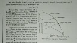
Induction Motor, , 1271, , Let the normal voltage be V1 volts., Speed in second case, = 97/2 = 48.5 r.p.m., ∴, slip = (100 − 48.5)/100 = 0.515 or 51.5%, Now,, , T =, , k Φ sE2 R2, , R22 + (sX 2 )2, Since torque is the same in both cases,, kV12 s1R2, R22 + (s1 X 2 )2, V1 , V , 2, , ∴, , =, , 2, , =, , ksV 2 R2, , (3 E2 ∝ Φ ∝ V), , R22 + (sX 2 ) 2, , kV22 s2 R2, R22 + (s2 X 2 )2, , where V2 = stator voltage in second case, , =, , s2 R22 + (s1 X 2 )2, ., s1 R 2 + (s X )2, 2, 2 2, , =, , 2, 2, 51.3 . 0.015 + (0.03 × 0.09), = 1.68, 2, 3 0.015 + (0.515 × 0.09)2, , V1, V − V2 0.296, =, = 1.68 = 1.296 or 1, V2, 1.296, V1, Hence, percentage, reduction in stator (or supply voltage) is, V − V2, 0.296 × 100, × 100 =, = 1, = 22.84%, 1.296, V1, In the second case,, tan φ = s2 X2/R2 = 0.515 × 0.09/0.015 = 3.09, ∴, , −1, , ∴, , φ = tan (3.09) = 72°4′ and p.f. = cos φ = cos 72°4′ = 0.31, , 34.27. Tor, que/Speed Cur, ve, orque/Speed, Curv, The torque developed by a conventional 3-phase motor depends on its speed but the relation between, the two cannot be represented by a simple equation. It is easier to show the relationship in the form of a, curve (Fig. 34.22). In this diagram, T represents the nominal full-load torque of the motor. As seen, the, starting torque (at N = 0) is 1.5 T and the maximum torque (also called breakdown torque) is 2.5 T., , Torque, , 2.5T, , 1.5T, T, , 0, 0, , Locked-Rotor, Torque, , Breakdown, Torque, , Pull-up, Torque, , 20, , Full, Load, , 60, 40, Rotational Speed, %, , 80, , 100, N NS, , Fig. 34.22, , At full-load, the motor runs at a speed of N. When mechanical load increases, motor speed, decreases till the motor torque again becomes equal to the load torque. As long as the two torques are, in balance, the motor will run at constant (but lower) speed. However, if the load torque exceeds 2.5 T,, the motor will suddenly stop.
Page 30 :
1272, , Electrical Technology, , 34.28. Sha, pe of Tor, que/Speed Cur, ve, Shape, orque/Speed, Curv, , 150, Motor, , 75, , Generator, , 45 A, Break, 900 450 0, 75, , Torque (N-m), , Torque (N-m), , For a squirrel-cage induction motor (SCIM), shape of its torque/speed curve depends on the voltage, 2, and frequency applied to its stator. If f is fixed, T ∝ V (Art 34.22). Also, synchronous speed, , 150, , 110 V, 15 Hz, , 440 V, 60 Hz, , 660 V, 90 Hz, , 75, Break 45, , 450, , 900 13501800 2250 2700, Speed (r.p.m.), , 900 450 0, 75, , 150, , 450, , 900 13501800 2250 2700, Speed (r.p.m.), , 150, (a), , (b ), Fig. 34.23, , depends on the supply frequency. Now, let us see what happens when both stator voltage and, frequency are changed. In practice, supply voltage and frequency are varied in the same proportion, in order to maintain a constant flux in the air-gap. For example, if voltage is doubled, then frequency, is also doubled. Under these conditions, shape of the torque/speed curve remains the same but its, position along the X-axis (i.e.speed axis) shifts with frequency., Fig. 34.23 (a) shows the torque/speed curve of an 11.kW, 440-V, 60-Hz 3-φ SCIM. As seen, fullload speed is 1728 rpm and full-load torque is 45 N-m (point-A) whereas breakdown torque is, 150 N-m and locked-rotor torque is 75 N–m., Suppose, we now reduce both the voltage and fequency to one-fourth their original values i.e. to, 110 V and 15 Hz respectively. As seen in Fig. 34.23 (b), the torque/speed curve shifts to the left. Now,, the curve crosses the X-axis at the synchronous speed of 120 × 15/4 = 450 rpm (i.e. 1800/4 = 450 rpm)., Similarly, if the voltage and frequency are increased by 50% (660 V 90 Hz), the curve shifts to the right, and cuts the X-axis at the synchronous speed of 2700 rpm., Since the shape of the torque/speed curve remains the same at all frequencies, it follows that, torque developed by a SCIM is the same whenever slip-speed is the same., Exampel 34.26. A 440-V, 50-Hz, 4-pole, 3-phase SCIM develops a torque of 100 N-m at a speed, of 1200 rpm. If the stator supply frequency is reduced by half, calculate, (a) the stator supply voltage required for maintaining the same flux in the machine., (b) the new speed at a torque of 100 N-m., Solution. (a) The stator voltage must be reduced in proportion to the frequency. Hence, it should, also be reduced by half to 440/2 = 220 V., (b) Synchronous speed at 50 Hz frequency = 120 × 50/4 = 1500 rpm. Hence, slip speed for a, torque of 100 N-m = 1500 − 1200 = 300 rpm., Now, synchronous speed at 25 Hz = 1500/2 = 750 rpm., Since slip-speed has to be the same for the same torque irrespective of the frequency, the new, speed at 100 N-m is = 750 + 300 = 1050 rpm., , 34.29. Current/Speed Curve of an Induction Motor, It is a V-shaped curve having a minimum value at synchronous speed. This minimum is equal to
Page 31 :
Induction Motor, , 1273, , Stator, Current, , N-m, A, 150, , Torque, , the magnetising current which is needed to create flux in the machine. Since flux is purposely kept constant,, it means that magnetising current is the same at all synchronous speeds., , 100, , 75, , 900, , 1350, , 450, , 0, , 450, , 900, , 1350 1800, , 2250, , 2700, , 3150, , 3600, , Speed, 75, , 150, Fig. 34.24, , Torque, , Stator Current, Torque, , Fig. 34.24. shows the current/speed curve, N-m, of the SCIM discussed in Art. 34.28 above., A, 150 T15, Refer Fig. 34.23(b) and Fig. 34.24, As seen,, T60, locked rotor current is 100 A and the, corresponding torque is 75 N-m. If stator, 100, I60, voltage and frequency are varied in the same, 75, proportion, current/speed curve has the same, I15, shape, but shifts along the speed axis. Suppose, that voltage and frequency are reduced to onefourth of their previous values i.e. to 110 V, 15, 0, 450 900 1350 1800 2250 2700, Hz respectively. Then, locked rotor current, Speed (r.p.m.), decreases to 75 A but corresponding torque, Fig. 34.25, increases to 150 N-m which is equal to full, breakdown torque (Fig. 34.25). It means that by reducing frequency, we can obtain a larger torque, with a reduced current. This is one of the big advantages of frequency control method. By, progressively increasing the voltage and current during the start-up period, a SCIM can be made to, develop close to its breakdown torque all the way from zero to rated speed., Another advantage of frequency control is that, Breakdown, it permits regenerative braking of the motor. In, Torque, fact, the main reason for the popularity of, frequency-controlled induction motor drives is, their ability to develop high torque from zero to, 1, T1, full speed together with the economy of, 2, regenerative braking., T2, , 34.30. Tor, que/Speed Character, orque/Speed, Character-istic Under Load, 0, , 0, Speed, Fig. 34.26, , N2 N1, , NS, , As stated earlier, stable operation of an induction, motor lies over the linear portion of its torque/, speed curve. The slope of this straight line depends
Page 32 :
1274, , Electrical Technology, , mainly on the rotor resistance. Higher the resistance, sharper the slope. This linear relationship between, torque and speed (Fig. 34.26) enables us to establish a very simple equation between different, parameters of an induction motor. The parameters under two different load conditions are related by, the equation, s2 = s1 ., , T2 R2 V1 , ., T1 R1 V2 , , 2, , ...(i), , The only restriction in applying the above equation is that the new torque T2 must not be greater than T1, (V2/V1)2. In that case, the above equation yields an accuracy of better than 5% which is sufficient for all, practical purposes., Example 34.24. A 400-V, 60-Hz, 8-pole, 3-φ induction motor runs at a speed of 1140 rpm when, connected to a 440-V line. Calculate the speed if voltage increases to 550V., Solution. Here, s1 = (1200 − 1140)/1200 = 0.05. Since everything else remains the same in Eq. (i), of Art. 34.30 except the slip and voltage, hence, S 2 = s1(V1/V2)2 = 0.05 × (440/550)2 = 0.032, ...Art. 34.23, ∴, N2 = 1200(1 − 0.032) = 1161.6 rpm., Example 34.25. A 450.V, 60.Hz, 8-Pole, 3-phase induction motor runs at 873 rpm when driving, a fan. The initial rotor temperature is 23°C. The speed drops to 864 rpm when the motor reaches its, final temperature. Calculate (i) increase in rotor resistance and (ii) approximate temperature of the, hot rotor if temperature coefficient of resistance is 1/234 per °C., Solution. s1 = (900 − 873)/900 = 0.03 and s2 = (900 − 864)/900 = 0.04, Since voltage and frequency etc. are fixed, the change in speed is entirely due to change in rotor, resistance., (i) s2 = s1(R2/R1) or 0.04 = 0.03 (R2/R1); R2 = 1.33 R1, Obviously, the rotor resistance has increased by 33 percent., (ii) Let t2 be temperature of the rotor. Then, as seen from Art.1-11,, 1, , , R2 = R1 [1 + α (t2 − 23)] or 1.33 R1 = R1 1 + 234 (t2 − 23) , ∴ t2 = 100.2°C, , , , 34.31. Plugging of an Induction Motor, An induction motor can be quickly stopped by, simply inter-changing any of its two stator leads. It, reverses the direction of the revolving flux which, produces a torque in the reverse direction, thus, Pf, , Pcs, , P1, , Pcr, , Pw, Pm, , P2, , Rotor, , Stator, Fig. 34.27, , Induction asynchronous motor, , applying brake on the motor. Obviously, during, this so-called plugging period, the motor acts as, a brake. It absorbs kinetic energy from the still
Page 33 :
Induction Motor, , 1275, , revolving load causing its speed to fall. The associated Power Pm is dissipated as heat in the rotor. At the, same time, the rotor also continues to receive power P2 from the stator (Fig. 34.27) which is also dissipated, as heat. Consequently, plugging produces rotor I 2R losses which even exceed those when the rotor is, locked., , 34.32. Induction Motor Operating as a Generator, When run faster than its synchronous speed, an induction motor runs as a generator called a Induction, generator. It converts the mechanical energy it receives into electrical energy and this energy is released by, the stator (Fig. 34.29). Fig. 34.28 shows an ordinary squirrel-cage motor which is driven by a petrol engine, and is connected to a 3-phase line. As soon as motor speed exceeds its synchronous speed, it starts, delivering active power P to the 3-phase line. However, for creating its own magnetic field, it absorbs, reactive power Q from the line to which it is connected. As seen, Q flows in the opposite direction to P., , Fig. 34.28, , Fig. 34.29, , The active power is directly proportional to the slip above the synchronous speed. The reactive, power required by the machine can also be supplied by a group of capacitors connected across its, terminals (Fig. 34.30). This arrangement can be used to supply a 3-phase load without using an, external source. The frequency generated is slightly less than that corresponding to the speed of, rotation., , Fig. 34.30, , The terminal voltage increases with capacitance. If capacitance is insufficient, the generator, voltage will not build up. Hence, capacitor bank must be large enough to supply the reactive power, normally drawn by the motor., Example 34.26. A 440-V, 4-pole, 1470 rpm. 30-kW, 3-phase induction motor is to be used as an, asynchronous generator. The rated current of the motor is 40 A and full-load power factor is 85%., Calculate, (a) capacitance required per phase if capacitors are connected in delta., (b) speed of the driving engine for generating a frequency of 50 Hz., Solution. (i), , S =, , 3 .VI = 1.73 × 440 × 40 = 30.4 kVA
Page 34 :
1276, , Electrical Technology, P = S cos φ = 30.4 × 0.85 = 25.8 kW, Q =, , 2, 2, 2, 2, S − P = 30.4 − 25.8 = 16 kVAR, , Hence, the ∆-connected capacitor bank (Fig. 32.31) must provide 16/3 = 5.333 kVAR per phase., Capacitor current per phase is = 5,333/440, = 12 A. Hence Xc = 440/12 = 36.6 Ω. Now,, 1, C=, 2 π f X C = 1/2π × 50 × 36.6 = 87µF, (ii) The driving engine must run at slightly, more than synchronous speed. The slip speed, is usually the same as that when the machine, runs as a motor i.e. 30 rpm., Hence, engine speed is = 1500 + 30 =, 1530 rpm., , Fig. 34.31, , 34.33. Complete Tor, que/Speed Cur, ve of a Thr, ee-Phase Machine, orque/Speed, Curv, Three-Phase, We have already seen that a 3-phase machine can be run as a motor, when it takes electric power and, supplies mechanical power. The directions of torque and rotor rotation are in the same direction. The same, machine can be used as an asynchronous generator when driven at a speed greater than the synchronous, speed. In this case, it receives mechanical energy in the rotor and supplies electrical energy from the stator., The torque and speed are oppositely-directed., The same machine can also be used as a brake during the plugging period (Art. 34.31). The three, modes of operation are depicted in the torque/speed curve shown in Fig. 34.32., Torque, , Pcs Pf, P1, , S, , Pcs Pf, , Pcr, , P2, , Pm, , Motor, , Brake, _N, , Pcr Pw, , 0, , Pcs Pf, , Pw, , P1, , NS, Pcr Pw, , P1, Pm, , P2, NS, , Pm, , P2, NS, , T, , +2NS, Generator, , T N, , N, , NS, N, T, , Fig. 34.32, , Tutor, ial Pr, oblem No. 34.2, utorial, Problem, 1. In a 3-phase, slip-ring induction motor, the open-circuit voltage across slip-rings is measured to be, 110 V with normal voltage applied to the stator. The rotor is star-connected and has a resistance of, 1 Ω and reactance of 4 Ω at standstill condition. Find the rotor current when the machine is (a) at, standstill with slip-rings joined to a star-connected starter with a resistance of 2Ω per phase and, negligible reactance (b) running normally with 5% slip. State any assumptions made., [12.7 A ; 3.11 A] (Electrical Technology-I, Bombay Univ. 1978)
Page 35 :
Induction Motor, , 1277, , 2. The star-connected rotor of an induction motor has a standstill impedance of (0.4 + j4) ohm per phase, and the rheostat impedance per phase is (6+j2) ohm. The motor has an induced e.m.f. of 80 V, between slip-rings at standstill when connected to its normal supply voltage. Find (a) rotor current at, standstill with the rheostat in the circuit (b) when the slip-rings are short-circuited and the motor is, running with a slip of 3%., [5.27 A ; 3.3 A], 3. A 4-pole, 50-Hz induction motor has a full-load slip of 5%. Each rotor phase has a resistance of 0.3 Ω, and a standstill reactance of 1.2 Ω. Find the ratio of maximum torque to full-load torque and the speed, at which maximum torque occurs., [2.6 ; 1125 r.p.m.], 4. A 3-phase, 4-pole, 50-Hz induction motor has a star-connected rotor. The voltage of each rotor phase, at standstill and on open-circuit is 121 V. The rotor resistance per phase is 0.3 Ω and the reactance at, standstill is 0.8 Ω. If the rotor current is 15 A, calculate the speed at which the motor is running., Also, calculate the speed at which the torque is a maximum and the corresponding value of the input, power to the motor, assuming the flux to remain constant., [1444 r.p.m.; 937.5 r.p.m.], 5. A 4-pole, 3-phase, 50 Hz induction motor has a voltage between slip-rings on open-circuit of 520 V., The star-connected rotor has a standstill reactance and resistance of 2.0 and 0.4 Ω per phase, respectively. Determine :, (a) the full-load torque if full-load speed is 1,425 r.p.m., (b) the ratio of starting torque to full-load torque, (c) the additional rotor resistance required to give maximum torque at standstill, [(a) 200 N-m (b) 0.82 (c) 1.6 Ω] (Elect. Machines-II, Vikram Univ. Ujjain 1977), 6. A 50-Hz, 8-pole induction motor has a full-load slip of 4 per cent. The rotor resistance is 0.001 Ω, per phase and standstill reactance is 0.005 Ω per phase. Find the ratio of the maximum to the fullload torque and the speed at which the maximum torque occurs., [2.6; 600 r.p.m.] (City & Guilds, London), 7. A 3-φ, 50-Hz induction motor with its rotor star-connected gives 500 V (r.m.s.) at standstill between, slip-rings on open circuit. Calculate the current and power factor in each phase of the rotor windings, at standstill when joined to a star-connected circuit, each limb of which has a resistance of 10 Ω and, an inductance of 0.03 H. The resistance per phase of the rotor windings is 0.2 Ω and inductance, 0.03 H. Calculate also the current and power factor in each rotor phase when the rings are shortcircuited and the motor is running with a slip of 4 per cent., [13.6 A, 0.48; 27.0 A, 0.47] (London University), 8. A 4-pole, 50-Hz, 3-phase induction motor has a slip-ring rotor with a resistance and standstill reactance, of 0.04 Ω and 0.2 Ω per phase respectively. Find the amount of resistance to be inserted in each rotor, phase to obtain full-load torque at starting. What will be the approximate power factor in the rotor at, this instant ? The slip at full-load is 3 per cent., [0.084 Ω, 0.516 p.f.] (London University), 9. A 3-φ induction motor has a synchronous speed of 250 r.p.m. and 4 per cent slip at full-load. The, rotor has a resistance of 0.02 Ω/phase and a standstill leakage reactance of 0.15 Ω/phase. Calculate, (a) the ratio of maximum and full-load torque (b) the speed at which the maximum torque is developed. Neglect resistance and leakage of the stator winding., [(a) 1.82 (b) 217 r.p.m.] (London University), 10. The rotor of an 8-pole, 50-Hz, 3-phase induction motor has a resistance of 0.2 Ω/phase and runs at, 720 r.p.m. If the load torque remains unchanged. Calculate the additional rotor resistance that will, reduce this speed by 10%, [0.8 Ω] (City & Guilds, London), 11. A 3-phase induction motor has a rotor for which the resistance per phase is 0.1 Ω and the reactance, per phase when stationary is 0.4 Ω. The rotor induced e.m.f. per phase is 100 V when stationary., Calculate the rotor current and rotor power factor (a) when stationary (b) when running with a slip, of 5 per cent., [(a) 242.5 A; 0.243 (b) 49 A; 0.98], 12. An induction motor with 3-phase star-connected rotor has a rotor resistance and standstill reactance, of 0.1 Ω and 0.5 Ω respectively. The slip-rings are connected to a star-connected resistance of 0.2, Ω per phase. If the standstill voltage between slip-rings is 200 volts, calculate the rotor current per, phase when the slip is 5%, the resistance being still in circuit., [19.1 A], 13. A 3-phase, 50-Hz induction motor has its rotor windings connected in star. At the moment of starting
Page 36 :
1278, , Electrical Technology, , the rotor, induced e.m.f. between each pair of slip-rings is 350 V. The rotor resistance per phase is, 0.2 Ω and the standstill reactance per phase is 1 Ω. Calculate the rotor starting current if the external, starting resistance per phase is 8 Ω and also the rotor current when running with slip-rings shortcircuited, the slip being 3 per cent., [24.5 A ; 30.0 A], 14. In a certain 8-pole, 50-Hz machine, the rotor resistance per phase is 0.04 Ω and the maximum torque, occurs at a speed of 645 r.p.m. Assuming that the air-gap flux is constant at all loads, determine the, percentage of maximum torque (a) at starting (b) when the slip is 3%., [(a) 0.273 (b) 0.41] (London University), 15. A 6-pole, 3-phase, 50-Hz induction motor has rotor resistance and reactance of 0.02 Ω and 0.1 Ω, respectively per phase. At what speed would it develop maximum torque ? Find out the value of, resistance necessary to give half of maximum torque at starting., [800 rpm; 0.007 Ω] (Elect.Engg. Grad I.E.T.E. June 1988), , 34.34. Measurement of Slip, , Torque, , B, A, D C, Following are some of the methods used for findRator Rator, Syning the slip of an induction motor whether squirrelSlip Speed, chrocage or slip-ring type., nous, Speed, (i) By actual measurement of motor speed, This method requires measurement of actual motor speed N and calculation of synchronous speed, Ns. N is measured with the help of a speedometer, Speed, and Ns calculated from the knowledge of supply frequency and the number of poles of the motor.* Then The speed curve of an induction motor. The slip is, the difference in rotor speed relative to that of the, slip can be calculated by using the equation., synchronous speed. CD = AD - BD = AB., s = (Ns − N) × 100/Ns, (ii) By comparing rotor and stator supply frequencies, This method is based on the fact that s = fr /f, Since f is generally known, s can be found if frequency of rotor current can be measured by some, method. In the usual case, where f is 50 Hz, fr is so low that individual cycles can be easily counted. For this, purpose, a d.c. moving-coil millivoltmeter, preferably of centre-zero, is employed as described below :, (a) In the case of a slip-ring motor, the leads of the millivoltmeter are lightly pressed against the, adjacent slip-rings as they revolve (Fig. 34.33). Usually, there is sufficient voltage drop in the brushes, and their short-circuiting strap to provide an indication on the millivoltmeter. The current in the, millivoltmeter follows the variations of the rotor current and hence the pointer oscillates about its, mean zero position. The number of, complete cycles made by the pointer, per second can be easily counted (it is, worth remembering that one cycle, R, consists of a movement from zero to a, maximum to the right, back to zero and, mV, mV, on to a maximum to the left and then, R, back to zero)., As an example, consider the case, of a 4-pole motor fed from a 50-Hz supFig. 34.33, Fig. 34.34, ply and running at 1,425 r.p.m. Since, , *, , Since an induction motor does not have salient poles, the number of poles is usually inferred from the, no-load speed or from the rated speed of the motor.
Page 37 :
Induction Motor, , 1279, , Ns = 1,500 r.p.m., its slip is 5% or 0.05. The frequency of the rotor current would be fr = sf = 0.05 × 50 =, 2.5 Hz which (being slow enough) can be easily counted., (b) For squirrel-cage motors (which do not have slip-rings) it is not possible to employ the millivoltmeter, so directly, although it is sometimes possible to pick up some voltage by connecting the millivoltmeter, across the ends of the motor shaft (Fig. 34.34), Another method, sometime employed, is as follows :, A large flat search coil of many turns is placed centrally against the end plate on the non-driving end of, the motor. Quite often, it is possible to pick up sufficient voltage by induction from the leakage fluxes to, obtain a reading on the millivoltmeter. Obviously, a large 50-Hz voltage will also be induced in the search, coil although it is too rapid to affect the millivoltmeter. Commercial slip-indicators use such a search coil, and, in addition, contain a low-pass filter amplifier for eliminating fundamental frequency and a bridge circuit, for comparing stator and rotor current frequencies., (iii) Stroboscopic Method, In this method, a circular metallic disc is taken and painted with alternately black and white segments., The number of segments (both black and white) is equal to the number of poles of the motor. For a 6-pole, motor, there will be six segments, three black and three white, as shown in, Fig. 34.35(a). The painted disc is mounted, on the end of the shaft and illuminated by, means of a neon-filled stroboscopic lamp,, Motor, which may be supplied preferably with a, combined d.c. and a.c. supply although only, a.c. supply will do*. The connections for, combined supply are shown in Fig. 34.36, whereas Fig. 34.35 (b) shows the, (b), (a), connection for a.c. supply only. It must be, Fig. 34.35, noted that with combined d.c. and a.c., supply, the lamp will flash once per, cycle**. But with a.c. supply, it will flash twice per cycle., Consider the case when the revolving disc is seen in the flash light of the bulb which is fed by the, combined d.c. and a.c. supply., If the disc were to rotate at synchronous speed, it would appear to be stationary. Since, in actual, practice, its speed is slightly less than the synchronous speed, it appears to rotate slowly backwards., The reason for this apparent backward movement is as follows :, , Fig. 34.36, , *, **, , When combined d.c. and a.c. supply is used, the lamp should be tried both ways in its socket to see which, way it gives better light., It will flash only when the two voltages add and remain extinguished when they oppose.
Page 38 :
1280, , Electrical Technology, , Let Fig. 34.37(a) represent the position of, the white lines when they are illuminated by the, first flash. When the next flash comes, they have, nearly reached positions 120° ahead (but not, quite), as shown in Fig. 34.37(b). Hence, line, No. 1 has almost reached the position previously occupied by line No. 2 and one flash still, later [Fig. 34.37 (c)] it has nearly reached the, Fig. 34.37, position previously occupied by line No. 3 in, Fig. 34.37(a)., By counting the number of lines passing a fixed point in, say, a minute and dividing by the number of, lines seen (i.e. three in the case of a 6-pole motor and so on) the apparent backward speed in r.p.m. can be, found. This gives slip-speed in r.p.m. i.e. N s − N. The slip may be found from the, relation s =, , NS − N, × 100, NS, , Note. If the lamp is fed with a.c. supply alone, then it will flash twice per cycle and twice as many lines will, be seen rotating as before., , 34.35. Power Stages in an Induction Motor, Stator iron loss (consisting of eddy and hysteresis losses) depends on the supply frequency and, the flux density in the iron core. It is practically constant. The iron loss of the rotor is, however,, negligible because frequency of rotor currents under normal running conditions is always small. Total, 2, rotor Cu loss = 3 I2 R2., Different stages of power development in an induction motor are as under :, , Motor, Input in, Stator, P1, , Stator, Cu &, Iron, Losses, , Rotor, Input, P2, , Rotor, Cu, Loss, , Mech. Power, Developed, in Rotor, Pm, or Gross, Torque, Tg, , Windage, and, Friction, Losses, , Rotor, Output, Pout, or, BHP, , A better visual for power flow, within an induction motor, is given in Fig. 34.38., , 34.36. Tor, que De, veloped b, y an Induction Motor, orque, Dev, by, An induction motor develops gross torque Tg due to gross rotor output Pm (Fig 34.38). Its value can, be expressed either in terms of rotor input P2 or rotor gross output Pm as given below., Tg =, , P2, P2, =, ωs 2π N s, , ...in terms of rotor input
Page 39 :
Induction Motor, , 1281, , w, , Fig. 34.38, , Tg =, , Pm, P, = m, ω 2π N, , ... in terms of rotor output, , The shaft torque Tsh is due to output power Pout which is less than Pm because of rotor friction and, windage losses., ∴, Tsh = Pout/ω = Pout/2πN, The difference between Tg and Tsh equals the torque lost due to friction and windage loss in the, motor., In the above expressions, N and Ns are in r.p.s. However, if they are in r.p.m., the above expressions, for motor torque become, P2, 60 . P2 9.55 P2 N-m, =, =, Tg =, 2 π N s / 60 2π N s, Ns, Pm, P, P, = 60 . m = 9.55 m N-m, =, 2 π N / 60 2π N, N, Pout, P, P, Tsh =, = 60 . out = 9.55 out N-m, 2πN / 60 2π N, N, , 34.37. Tor, que, Mechanical P, ower and Rotor Output, orque,, Po, Stator input, P1 = stator output + stator losses, The stator output is transferred entirely inductively to the rotor circuit.
Page 40 :
1282, , Electrical Technology, , Obviously, rotor input, Rotor gross output,, , P 2 = stator output, P m = rotor input P2 — rotor Cu losses, This rotor output is converted into mechanical energy and gives rise to gross torque Tg. Out of this, gross torque developed, some is lost due to windage and friction losses in the rotor and the rest appears as the useful or shaft torque Tsh., Let N r.p.s. be the actual speed of the rotor and if, Tg is in N-m, then, , The type DF200 diesel electric locomotive is the first, motor-driven train equipped with diesel generators since, 1958. It adopted induction motors to realize high acceleration, high speed, and large torque, which resulted in, a quick-response generator brake system., , ∴, , Tg =, , Tg × 2 πN = rotor gross output in watts, Pm, rotor gross output in watts, Pm, ∴ Tg =, N-m*, 2π N, ...(1), If there were no Cu losses in the rotor, then rotor, output will equal rotor input and the rotor will run, at synchronous speed., , rotor input P2, 2π N S, , From (1) and (2), we get,, Rotor gross output, P m = Tg ω = Tg × 2 πN, Rotor input, P 2 = Tg ωs = Tg × 2 πNs, The difference of two equals rotor Cu loss., ∴ rotor Cu loss, = P2 − Pm = Tg × 2 π (Ns − N), rotor Cu loss N s − N, =, =s, From (3) and (4),, rotor input, Ns, ∴ rotor Cu loss, Also, rotor input, Rotor gross output,, , ...(2), , ...(3), ...(4), , s × rotor input = s × power across air-gap = s P2, ...(5), rotor Cu loss/s, Pm, input P2 − rotor Cu loss = input − s × rotor input, (1 − s) input P2, ...(6), ∴ rotor gross output, Pm, (1 − s) rotor input P2, Pm N, rotor gross output, Pm, N ;, or, = 1−s=, =, N, P2 N s, rotor input, P2, s, N, rotor Cu loss, ∴, rotor efficiency =, Also,, = s, Ns, rotor gross output, 1− s, Important Conclusion, If some power P2 is delivered to a rotor, then a part sP2 is lost in the rotor itself as copper loss (and, appears as heat) and the remaining (1 − s)P2 appears as gross mechanical power Pm (including friction, and windage losses)., 2, ∴ P2 : Pm : I R : : 1 : (1 − s) : s or P2 : Pm : Pcr : : 1 : (1 − s) : s, *, , =, =, =, =, =, , The value of gross torque in kg-m is given by, Tg =, , Pm, rotor gross output in watts, kg-m. =, kg-m, 9.81× 2πN, 9.81 × 2πN
Page 41 :
Induction Motor, , 1283, , The rotor input power will always divide itself in this ratio, hence it is advantageous to run the motor, with as small a slip as possible., Example 34.27. The power input to the rotor of 440 V, 50 Hz, 6-pole, 3-phase, induction motor is 80, kW. The rotor electromotive force is observed to make 100 complete alterations per minute. Calculate, (i) the slip, (ii) the rotor speed, (iii) rotor copper losses per phase., [Madras University, 1997], Solution. 100 alterations/minute = 100 cycles/sec, 60, 1.6667 Hz = sf, 1.6667 =, Hence, the slip,, s =, 0.3333 P.u. or 3.333%, 50, (ii) rotor speed,, N = (1 − s) NS = (1 − 0.03333) × 1000, Since, , Ns =, , 120 × 50, = 1000 rpm, N = 966.67 rpm, 6, , 1 × (s × rotor input), 3, total rotor power input = 80 kW, rotor power input per phase = 80/3 kW, rotor copper losses per phase, 0.0333 × 80, kW = 0.8888 kW, =, 3, , (iii) rotor copper losses/phase, , =, , Example 34.28. A 440-V, 3-φ, 50-Hz, 4-pole, Y-connected induction motor has a full-load speed of, 1425 rpm. The rotor has an impedance of (0.4 + J 4) ohm and rotor/stator turn ratio of 0.8. Calculate (i) full-load torque (ii) rotor current and full-load rotor Cu loss (iii ) power output if windage, and friction losses amount to 500 W (iv) maximum torque and the speed at which it occurs, (v) starting current and (vi) starting torque., Solution., , Ns = 120 × 50/4 = 1500 rpm = 25 rps, s = 75/1500 = 0.05, E 1 = 440/1.73 = 254 V/phase, , (i) Full-load, , Tf =, , (ii), , 2, 3 × 0.05 (0.8 × 254) × 0.4, 2, 2π × 25, (0.4) + (0.05 × 4)2, = 78.87 N-m, sE2, sKE1, 0.05 × (0.8 × 254), Ir =, =, =, 2, 2, 2, 2, 2, 2, (0.4) + (0.05 × 4), R2 + (sX 2 ), R2 + (sX 2 ), , =, Total Cu loss, =, (iii) Now,, Pm =, ∴, Pout =, (iv) For maximum torque,, s =, ∴, , Tmax =, , 22.73 A, 2, 2, 3Ir R = 3 × 22.73 × 0.4 = 620 W, 2πNT = 2 π × (1425/60) × 78.87 = 11,745 Ω, Pm − windage and friction loss =11,745 − 500 = 11,245 W, R2/X2 = 0.4/4 = 0.1, , 0.1 × (0.8 × 254)2 × 0.4, 3, = 98.5 N-m, ×, 2π × 25, (0.4)2 + (0.1 × 4)2, , Since, s = 0.1, slip speed = s Ns = 0.1 × 1500 = 150 rpm., ∴ Speed for maximum torque = 1500 − 150 = 1350 rpm.
Page 42 :
1284, , Electrical Technology, , (v) starting current, , =, , E2, , +, s = 1, hence, , (vi) At start,, , Tst =, , 2, R2, , 2, X2, , KE1, , =, , 2, R2, , +, , 2, X2, , =, , 0.8 × 254, 0.4 + 4, 2, , 2, , = 50.5 A, , 2, 3 × (0.8 × 254) × 0.4 = 19.5 N-m, 2π × 25, (0.4)2 + 42, , It is seen that as compared to full-load torque, the starting torque is much less-almost 25 per cent., , 34.38. Induction Motor Tor, que Equa, tion, orque, Equation, The gross torque Tg developed by an induction motor is given by, Tg = P2 / 2 πNs, —Ns in r.p.s., = 60 P2 / 2πNs = 9.55 P2 /Ns —Ns in r.p.m., 2, Now,, P 2 = rotor Cu loss/s = 3I2 R2 /s, sE2, sKE1, =, As seen from Art. 34.19,, I2 =, 2, 2, 2, 2, R2 + (s X 2 ), R2 + (s X 2 ), where K is rotor/stator turn ratio per phase., 2, , ∴, , P2 = 3 ×, , Also,, , P2 = 3 ×, , ∴, , Tg =, , 2, , 2, , s E2 R2, 2, 2, R2 + (s X 2 ), , ×, , 3 s E2 R2, 1, = 2, 2, s, R2 + (s X 2 ), , s 2 K 2 E12 R2, , 2 2, 1 = 3 s K E1 R2, ×, 2, 2, s R 2 + (s X )2, R2 + (s X 2 ), 2, 2, 2, , P2, s E2 R2, 3, =, ×, 2π N s 2 π N S R 2 + (s X ) 2, 2, 2, 2, , 2, , s K E1 R2, 3, ×, 2 π N S R 2 + (sX )2, 2, 2, Here, E1, E2, R2 and X2 represent phase values., or, , =, , — in terms of E2, — in terms of E1, , In fact, 3 K /2 π Ns = k is called the constant of the given machine. Hence, the above torque equation, may be simplified to, s E2R, Tg = k 2 1 2 2, — in terms of E1, R2 + (sX 2 ), 2, , 34.39. Synchr, onous Watt, Synchronous, It is clear from the above relations that torque is proportional to rotor input. By defining a new, unit of torque (instead of the force-at-radius unit), we can say that the rotor torque equals rotor input., The new unit is synchronous watt. When we say that a motor is developing a torque of 1,000, synchronous watts, we mean that the rotor input is 1,000 watts and that the torque is such that power, developed would be 1,000 watts provided the rotor were running synchronously and developing the, same torque., Or, Synchronous watt is that torque which, at the synchronous speed of the machine under consideration,, would develop a power of 1 watt., rotor input, P2, rotor input = Tsw × 2 π NS, ∴ Tsw =, 2π × synch. speed
Page 43 :
Induction Motor, , 1285, , 1 . NS . = 1 . NS ., P, P, ωs N g ωs N m, Synchronous wattage of an induction motor equals the power transferred across the air-gap, to the rotor., ∴ torque in synchronous watt, rotor Cu loss gross output power, Pm, = rotor input =, =, (1 − s), s, Obviously, at s = 1, torque in synchronous watt equals the total rotor Cu loss because at standstill,, entire rotor input is lost as Cu loss., Suppose a 23-kW, 4-pole induction motor has an efficiency of 92% and a speed of 1440 r.p.m. at, rated load. If mechanical losses are assumed to be about 25 per cent of the total losses, then, motor input = 23/0.92 = 25 kW, total loss = 25 − 23 = 2 kW., Friction and windage loss = 2/4 = 0.5 kW, ∴, Pm = 23 + 0.5 = 23.5 kW, Power in synchronous wattsPsw = P2 = 23.5 × 1500/1440 = 24.5 kW, synchronous speed, wS = 2 π (1500/60) = 157 rad / s, 3, ∴ synchronous torque, Tsw = 24.5 × 10 /157 = 156 N-m, N, 1, or, Tsw = Pm S . 1 = 23.5 × 1500 ×, 1440 2π (1500 / 60), N ωS, =, , = 156 N−m, , —Art 34.39, , 34.40. Var, ia, tions in Rotor Curr, ent, aria, iations, Current, The magnitude of the rotor current varies with load carried by the motor., As seen from Art. 34.37, rotor output, N, = N or rotor output = rotor input ×, NS, rotor input, NS, ∴, rotor input = rotor output × Ns / N, Also, rotor output ∝ 2 π N T = k N T, ∴, rotor input = k N T × Ns / N = k Ns T, 2, , Now,, ∴, , 3 I 2 R2, rotor Cu loss, = s or, = rotor input, s, rotor input, 3 I2 R2/s = k NsT or T ∝ I2 R2/s, 2, , 2, , Tst ∝ I22st R 2, 2, Tf ∝ I2 f R2 / sf, , — since s = 1, — sf = full-load slip, 2, , = s f I 2st , I2 f , where I2st and I2f are the rotor currents for starting and full-load running conditions., ∴, , Tst, Tf, , 34.41. Analogy with a Mechanical Clutch, We have seen above that, rotor Cu loss = slip × rotor input, This fact can be further clarified by considering the working of a mechanical clutch (though it is
Page 44 :
1286, , Electrical Technology, , not meant to be a proof for the above) similar to, the one used in automobiles. A plate clutch is shown, in Fig. 34.39. It is obvious that the torque on the, driving shaft must exactly equal the torque on the, driven shaft. In fact, these two torques are actually, one and the same torque, because the torque is, caused by friction between the discs and it is true, whether the clutch is slipping or not. Let ω1 and ω2, be the angular velocities of the shaft when the clutch, is slipping., Then, input = T ω1, and output = T, ω2 = T ω1(1 − s) : [ ω2 = ω1(1 − s)], loss = T ω1 − T ω2 = T ω1 − T ω1(1 − s) = sT ω1 = slip × input, , Fig. 34.39, , 34.42. Analogy with a D.C. Motor, The above relations could also be derived by comparing an induction motor with a d.c. motor. As, shown in Art 29.3, in a d.c. shunt motor, the applied voltage is always opposed by a back e.m.f. Eb. The, power developed in the motor armature is Eb Ia where Ia is armature current. This power, as we know, is, converted into mechanical power in the armature of the motor., Now, in an induction motor, it is seen that the induced e.m.f in the rotor decreases from its standstill, value of E2 to sE2 when in rotation. Obviously, the difference (1 − s) E2 is the e.m.f. called forth by the, rotation of the rotor similar to the back e.m.f. in a d.c. motor. Hence, gross power Pm developed in the, rotor is given by the product of the back e.m.f., armature current and rotor power factor., sE2, R2, Pm = (1 − s)E2 × I2 cos φ2 ;, Now I2 =, and cos φ2 =, 2, 2, 2, 2, [ R2 + (sX 2 ) ], [ R2 + (sX 2 ) ], ∴ Pm = (1 − s)E2 ×, , sE2, [R22 + (sX 2 )2 ], , ×, , R2, [R22 + (sX 2 ) 2 ], , =, , 2, s(1 − s)E2 R2, , R2 + (sX 2 ) 2, 2, , Multiplying the numerator and the denominator by s, we get, Pm =, , ( ), , 2, , 2, , ( ), , s E2, 1− s R, 1 − s I 2R, =, 2×, 2 2, 2, s, s, [R2 + (sX 2 )2 ], 2, , Now,, , I2 R2 = rotor Cu loss/phase, , , , sE2, 3 I =, , 2, 2, 2 , , [, +, (, ), ], R, sX, 2, 2, , , Cu loss, ∴, = s, rotor output 1 − s, , This is the same relationship as derived in Art. 34-37., Example 34.30. The power input to a 3-phase induction motor is 60 kW. The stator losses total, 1 kW. Find the mechanical power developed and the rotor copper loss per phase if the motor is, running with a slip of 3%., (Elect. Machines AMIE Sec. E Summer 1991), Solution. Rotor input,, , P 2 = stator input − stator losses = 60 − 1 = 59 kW, P m = (1 − s)P2 = (1 − 0.03) × 59 = 57.23 kW, , Total rotor Cu loss = sP2 = 0.03 × 59 = 1.77 kW = 1770 W, Rotor Cu loss/phase = 1770/3 = 590 W
Page 45 :
Induction Motor, , 1287, , Example 34.31. The power input to the rotor of a 400 V, 50.Hz, 6-pole, 3-phase induction motor, is 20 kW. The slip is 3%. Calculate (i) the frequency of rotor currents (ii) rotor speed (iii) rotor, copper losses and (iv) rotor resistance per phase if rotor current is 60 A., (Elect. Engg. Punjab Univ. 1991), Solution. (i) Frequency of rotor current = sf = 0.03 × 50 = 1.5 Hz, (ii) Ns = 120 × 50/6 = 1000 rpm; N = 1000(1 − 0.03) = 700 rpm, (iii) rotor Cu loss = s × rotor input = 0.03 × 20 = 0.6 kW = 600 W, 2, (iv) rotor Cu loss/phase = 200 W; ∴ 60 R2 = 200; R2 = 0.055 Ω, Example 34.32. A 3-phase, 6-pole, 50-Hz induction motor develops 3.73 kW at 960 rpm. What, will be the stator input if the stator loss is 280 W?, (Madurai Kamraj Univ. 1999), Solution. As seen from Art. 34.37,, , power developed in rotor, = N, rotor input, Ns, , Now, mechanical power developed in rotor = 3.73 kW., Ns = 120 × 50/6 = 1000 r.p.m., ∴, 3,730/rotor input = 960/1000, ∴ rotor input = 3,885 W, Stator input = rotor input + stator losses = 3885 + 280 = 4,156 W, Example 34.33. The power input to the rotor of a 400 V, 50-Hz, 6-pole, 3-φ induction motor is 75, kW. The rotor electromotive force is observed to make 100 complete alteration per minute. Calculate:, (i) slip (ii) rotor speed (iii) rotor copper losses per phase (iv) mechanical power developed., (Elect. Engg. I, Nagpur Univ. 1993), Solution. Frequency of rotor emf, f ′ = 100/60 = 5/3 Hz, (i) Now, f ′ = sf or 5/3 = s × 50; s = 1/30 = 0.033 or 3.33%, (ii) Ns = 120 × 50/6 = 1000 rpm ; N = Ns (1 − s) = 1000 (1 − 1/30) = 966.7 rpm, (iii) P2 = 75 kW ; total rotor Cu loss = sP2 = (1/30) × 75 = 2.5 kW, rotor Cu loss/phase = 2.5/3 = 0.833 kW, (iv) Pm = (1 − s)P2 = (1 − 1/30) × 75 = 72.5 kW, Example 34.34. The power input to a 500 V, 50-Hz, 6-pole, 3-phase induction motor running at, 975 rpm is 40 kW. The stator losses are 1 kW and the friction and windage losses total 2 kW., Calculate : (i) the slip (ii) the rotor copper loss (iii) shaft power and (iv) the efficiency., (Elect. Engg. - II, Pune Univ. 1989), Solution. (i) Ns = 120 × 50/6 = 1000 rpm ; s = (100 − 975)/1000 = 0.025 or 2.5%, (ii) Motor input P1=40 kW ; stator loss = 1 kW; rotor input P2 = 40 − 1 = 39 kW, ∴ rotor Cu loss = s × rotor input = 0.025 × 39 = 0.975 kW, (iii) Pm = P2 − rotor Cu loss = 39 − 0.975 = 38.025 kW, Pout = Pm − friction and windage loss = 38.025 − 2 = 36.025 kW, (iv) η = Pout/P1 = 36.025/40 = 0.9 or 90%, Example 34.35. A 100-kW (output), 3300-V, 50-Hz, 3-phase, star-connected induction motor, has a synchronous speed of 500 r.p.m. The full-load slip is 1.8% and F.L. power factor 0.85. Stator, copper loss = 2440 W. Iron loss = 3500 W. Rotational losses = 1200 W. Calculate (i) the rotor copper, loss (ii) the line current (iii) the full-load efficiency., (Elect. Machines, Nagpur Univ. 1993)
Page 46 :
1288, , Electrical Technology, , Solution. Pm = output + rotational loss = 100 + 1.2 = 101.2 kW, 0.018, s, (i), rotor Cu loss =, × Pm =, × 101.2 = 1.855 kW, 1 − 0.018, 1− s, (ii), rotor input, P2 = Pm + rotor Cu loss = 101.2 + 1.855 = 103.055 kW, Stator input = P2 + stator Cu and iron losses, = 103.055 + 2.44 + 3.5 = 108.995 kW, ∴, , 3 × 3300 × IL × 0.85;, The entire power flow in the motor is given below., , 108,995 =, , Stator, input, 108,995 W, , Stator, Cu & Iron, losses, 5940 W, (iii) F.L. efficiency, , Rotor, input, 103, 055 W, , IL= 22.4 A, , Mechanical, power, developed, in rotor, 101,200 W, Rotor, Cu loss, 1855 W, , Motor output, 100,000 W, or, 100 kW, Rotational, losses, 1200 W, , = 100,000/108,995 = 0.917 or 91.7%, , Example 34.36. The power input to the rotor of a 440 V, 50-Hz, 6-pole, 3-phase induction motor, is 100 kW. The rotor electromotive force is observed to make 120 cycles per minute, Calculate (i) the, slip (ii) the rotor speed (iii) mechanical power developed (iv) the rotor copper loss per phase and, (v) speed of stator field with respect to rotor., (Elect. Engg. AMIETE Sec. A June 1991), Solution. (i) f ′ = sf or (120/60) = s × 50; s = 0.01, (ii) Ns= 120 × 50/6 = 1000 rpm; N = 1000(1 − 0.01) = 990 rpm, (iii) Pm ( 1− s)P2 = (1− 0.01) × 100 = 99 kW, (iv) total rotor Cu loss = sP2 = 0.01 × 100 = 1 kW ; Cu loss/phase = 1/3 kW, (v) Ns= 1000 rpm; N = 990 rpm. Hence, speed of stator field with respect to rotor is, = 1000 − 990 = 10 rpm., Example 34.37. An induction motor has an efficiency of 0.9 when delivering an output of, 37 kW. At this load, the stator Cu loss and rotor Cu loss each equals the stator iron loss. The, mechanical losses are one-third of the no-load loss. Calculate the slip., (Adv. Elect. Machines, A.M.I.E. Sec. B Winter 1993), Solution. Motor input = 37,000/0.9 = 41,111 W, ∴ total loss = 41,111 − 37,000 = 4,111 W, This includes (i) stator Cu and iron losses (ii) rotor Cu loss (its iron loss being negligibly small), and (iii) rotor mechanical losses., Now, no-load loss of an induction motor consists of (i) stator iron loss and (ii) mechanical losses, provided we neglect the small amount of stator Cu loss under no-load condition. Moreover, these two, losses are independent of the load on the motor., no-load loss = Wi + Wm = 3Wm, ∴, Wm = Wi / 2, where Wi is the stator iron loss and Wm is the rotor mechanical losses., Let, stator iron loss = x; then stator Cu loss = x; rotor Cu loss = x; mechanical loss = x/2
Page 47 :
Induction Motor, , 1289, , ∴ 3x + x/2 = 4,111 or x = 1175 W, Now, rotor input = gross output + mechanical losses + rotor Cu loss, = 37,000 + (1175/2) + 1175 = 38,752 W, rotor Cu loss, s=, = 1175 = 0.03 or 3%., rotor input, 38,752, Example 34.38. A 400 V, 50-Hz, 6-pole, ∆-connected, 3-φ induction motor consumes 45 kW, with a line current of 75 A and runs at a slip of 3%. If stator iron loss is 1200 kW, windage and, fricition loss is 900 W and resistance between two stator terminals is 0.12 Ω, calculate (i) power, supplied to the rotor P2 (ii) rotor Cu loss Pcr (iii) power supplied to load Pout (iv) efficiency and (v), shaft torque developed., 45 × 1000, = 0.866 lag, 3 × 400 × 75, , Solution. Cos φ =, , A line current of 75 amp means a phase-current of 75, , 3 i.e. 43.3 amp, , Next, winding resistance has to be worked out, Refer to Fig. 34.40., r and 2r in parallel have an equivalent resistance measured at a, and b in delta connected motor as r × 2r/3r = 2r/3 ohms, 2 r = 0.12, r = 0.18, From the data given, 3, 2, Total stator copper loss = 3 × 43.3 × 0.18 = 1012, Fig. 34.40, Watts, Total input to stator = 45,000 Watts, Stator copper loss = 1012 Watts, stator core loss = 1200 Watts, Stator output = Rotor input = 42,788 Watts, Rotor copper loss = Slip × Rotor input = 0.03 × 42,788 = 1284 Watts, Rotor mech. output power= 42,788 − 1284 = 41,504 Watts, Shaft output = Mech. output of rotor − Mech losses, = 41504 − 900 = 40604 Watts, Efficiency = 40604 × 100% = 92.23%, 45000, 40604 × 60, Shaft output torque, T =, = 400 Nw-m, 2π × 970, Example 34.39(a). A 3-phase induction motor has a 4-pole, star-connected stator winding and, runs on a 220-V, 50-Hz supply. The rotor resistance per phase is 0.1 Ω and reactance 0.9 Ω . The, ratio of stator to rotor turns is 1.75. The full-load slip is 5%. Calculate for this load:, (a) the load torque in kg-m, (b) speed at maximum torque, (c) rotor e.m.f. at maximum torque., (Electrical Machines-I, South Gujarat Univ. 1985), Solution. (a) K = rotor turns/stator turns = 1/1.75, stator voltage/phase, E1 = 220, , 3V, 220 × 1, ∴ standstill rotor e.m.f./phase, E2 = K E1=, = 72.6 V, 3 1.75, Zr =, , R2 + ( sX 2 ) =, 2, , 2, , 0.1 + (0.05 × 0.9) = 0.11 Ω, 2, , 2
Page 48 :
1290, , Electrical Technology, , I2 = sE2 /Zr = 0.05 × 72.6/0.11 = 33 A, 2, 2, Rotor Cu loss, Pcr = 3I2 R2 = 3 × 33 × 0.1 = 327 W, rotor Cu loss, 327 = 0.05 ;, s ;, =, Pm = 6213 W, mech. power developed, 1− s, Pm 1 − 0.05, N = Ns (1 − s) = 1500 (1 − 0.05) = 1425 rpm, Tg = 9.55 Pm / N ;, ∴, Tg = 9.55 × 6213/1425 = 41.6 N-m = 41.6/9.81 = 4.24 kg.m, (b) For maximum torque, s m = R2 /X2 = 0.1/0.81 = 1/9, ∴, N = Ns (1 − s) = 1500(1 − 1/9) = 1333 r.p.m., (c) rotor e.m.f./phase at maximum torque = (1/9) × 72.6 = 8.07 V, Example 34.39 (b). A 400 V, 3-phase, 50 Hz, 4-pole, star-connected induction-motor takes a, line current of 10 A with 0.86 p. f. lagging. Its total stator losses are 5 % of the input. Rotor copper, losses are 4 % of the input to the rotor, and mechanical losses are 3 % of the input of the rotor., Calculate (i) slip and rotor speed, (ii) torque developed in the rotor, and (iii) shaft-torque., [Nagpur University, April 1998], 3 × 400 × 10 × 0.86 = 5958 Watts, Total stator losses = 5% of 5958 = 298 Watts, Rotor input = Stator Output = 5958 − 298 = 5660 Watts, Rotor Copper-loss = 4 % of 5660 = 226.4 Watts, Mechanical losses = 3% of 5660 = 169.8 Watts, Shaft output = 5660 − 226.4 − 169.8 = 5264 Watts, (i), slip, s = Rotor-copper-loss / rotor-input = 4 %, as given, Synchronous speed,, Ns = 120 × f/P =1500 rpm, Rotor speed,, N = Ns (1 − s) = 1500 (1 − 0.04) = 1440 rpm, (ii) Let the torque developed in the rotor = Tr, ωr’ Angular speed of rotor = 2π N/60 = 150.72 radians/sec, Rotor output = Rotor input − Rotor-copper-loss, = 5660 − 226.4 = 5433.6 watts, Trωr = 5433.6, giving Tr = 5433.6 / 150.72 = 36.05 Nw-m, (Alternatively, synchronous angular speed = ωs = 2π × 1500 / 60 = 157 rad / sec, Trωs = rotor input in Watts = 5660, Tr = 5660 / 157 = 36.05 Nw − m, (iii), Shaft-torque = Tm = Shaft output in Watts /ωr, = 5264 / 150.72 = 34.93 Nw − m., Example 34.40. A 3-phase, 440-V, 50-Hz, 40-pole, Y-connected induction motor has rotor, resistance of 0.1 Ω and reactance 0.9 Ω per phase. The ratio of stator to rotor turns is 3.5., Calculate:, (a) gross output at a slip of 5%, (b) the maximum torque in synchronous watts and the corresponding slip., , Solution., , Input to motor =, , 440 V, ; K = rotor turns = 1, stator turns 3.5, 3, Standstill e.m.f. per rotor phase is E2 = KE1 = 440 × 1 = 72.6 V, 3 3.5, , Solution. (a), , Phase voltage =
Page 49 :
Induction Motor, Er = s.E2 = 0.05 × 72.6 = 3.63 V ; Zr =, I2 =, , 3.63, Er, =, = 33.1 A ;, 0.1096, Zr, , 1291, , 0.12 + (0.05 × 0.9)2 = 0.1096 Ω, , Total Cu loss=3 I2 R = 3 × (33.1) × 0.1 = 330W, 2, , 2, , 330 × 0.95, rotor Cu loss = s, ∴ rotor gross output =, = 7,250 W, rotor gross output 1 − s, 0.05, (b) For Maximum Torque, R2 = sm . X2, ∴ sm = R2 /X2 = 0.1/0.9 = 1/9; Er = (1/9) × 72.6 = 8.07 V, Zr =, , 0.12 + (0.9 / 9)2 = 0.1414 Ω ; I2 = 8.07/0.1414 = 57.1 A, , Total rotor Cu loss = 3 × 57.1 × 0.1 = 978 W, 978, rotor input = rotor Cu loss =, = 8,802 W, 1/9, S, ∴ Maximum torque in synchronous watts = rotor input = 8,802 W, 2, , Example 34.41. An 18.65-kW, 4-pole, 50-Hz, 3-phase induction motor has friction and windage, losses of 2.5 per cent of the output. The full-load slip is 4%. Compute for full load (a) the rotor Cu, loss (b) the rotor input (c) the shaft torque (d) the gross electromagnetic torque., (Elect. Machines-II, Indore Univ. 1987), Solution. Motor output P out, Friction and windage loss Pw, Rotor gross output, Pm, rotor, Cu, loss, (a), rotor gross output, , = 18,650 W, = 2.5% of 18,650 = 466 W, = 18,650 + 466 = 19,116 W, = s , rotor Cu loss = 0.04 × 19,116 = 796.6 W, 1− s, (1 − 0.04), , (b) Rotor input, , P2 =, , rotor Cu loss, 796.5, =, = 19,912.5 W, s, 0.04, , (c) Tsh = 9.55 Pout / N :, , Ns, N, Tsh, Tg, , (or rotor input = 19,116 + 796.6 = 19,913 W), 120 × 50/4 = 1500 r.p.m., (1 − 0.04) × 1500 = 1440 r.p.m, 9.55 × 18,650/1440 = 123.7 N-m, 9.55 Pm /N = 9.55 × 19,116/1440 = 126.8 N-m, (or Tg = P2 /2 πNs = 19,913/2 π × 25 = 127 N-m), , ∴, (d) Gross torque, , =, =, =, =, , Example 34.42. An 8-pole, 3-phase, 50 Hz, induction motor is running at a speed of 710 rpm, with an input power of 35 kW. The stator losses at this operating condition are known to be 1200 W, while the rotational losses are 600 W. Find (i) the rotor copper loss, (ii) the gross torque developed,, (iii) the gross mechanical power developed, (iv) the net torque and (v) the mechanical power output., (Elect. Engg. AMIETE Sec. A 1991 & Rajiv Gandhi Techn. Univ., Bhopal, 2000), Solution. (i) P2 = 35 − 1.2 = 33.8 kW ; Ns = 120 × 50/8 = 750 rpm ; N = 710 rpm; s = (750 − 710)/, 750 = 0.0533, ∴, Rotor Cu loss = sP2 = 1.8 kW, (ii), (iii), , P m = P2 − rotor Cu loss = 33.8 - 1.8 = 32 kW, Tg = 9.55 Pm /N = 9.55 × 32000/710 = 430.42 N-m, , (iv), , Pout = Pm − rotational losses = 32000 − 600 = 31400 W
Page 50 :
1292, , Electrical Technology, , (v), , Tsh = 9.55 Pout /N = 9.55 × 31400/710 = 422.35 N-m, , Example 34.43. A 6-pole, 50-Hz, 3-phase, induction motor running on full-load with 4% slip, develops a torque of 149.3 N-m at its pulley rim. The friction and windage losses are 200 W and the, stator Cu and iron losses equal 1,620 W. Calculate (a) output power (b) the rotor Cu loss and (c) the, efficiency at full-load., (Elect. Technology, Mysore Univ. 1989), Solution., , Ns, Out put power, Now,, output, Friction and windage losses, Pm, P2, , =, =, =, =, =, , 120 × 50/6 = 1,000 r.p.m; N = (1 − 0.04) × 1,000 = 960 r.p.m., Tsh × 2 πN = 2 π × (960/60) × 149.3 = 15 kW, 15,000 W, 200 W ; Rotor gross output = 15,200 W, N, ∴ rotor input P2 = 15,200 × 1,000/960=15,833 W, NS, , (b) ∴, rotor Cu loss = 15,833 − 15,200 = 633 W, , rotor Cu loss, s , rotor Cu loss is given by : rotor output = 1 − s , , , (c), stator output = rotor input = 15,833 W, Stator Cu and iron losses = 1,620 W, ∴ Stator input, P 1 = 15,833 + 1,620 = 17,453 W, overall efficiency,, η = 15,000 × 100/17,453 = 86%, Example 34.44. An 18.65-kW, 6-pole, 50-Hz, 3-φ slip-ring induction motor runs at 960 r.p.m., on full-load with a rotor current per phase of 35 A. Allowing 1 kW for mechanical losses, find the, resistance per phase of 3-phase rotor winding., (Elect. Engg-I, Nagpur Univ. 1992), Solution., Motor output = 18.65 kW; Mechanical losses = 1 kW, ∴ Mechanical power developed by rotor, Pm = 18.65 + 1 = 19.65 kW, Now,, Ns = 120 × 50/6 = 1000 r.p.m. ;, s = (1000 − 960)/1000 = 0.04, s ×P, 0.04 × 19.65 = 0.819 kW = 819 W, =, rotor Cu loss =, 1 − s m (1 − 0.04), 2, 2, ∴, 3I2 R2 = 819 or 3 × 35 × R2 = 819, R2 = 0.023 Ω/phase, Example 34.45. A 400 V, 4-pole, 3-phase, 50-Hz induction motor has a rotor resistance and, reactance per phase of 0.01 Ω and 0.1 Ω respectively. Determine (a) maximum torque in N-m and, the corresponding slip (b) the full-load slip and power output in watts, if maximum torque is twice, the full-load torque. The ratio of stator to rotor turns is 4., Solution. Applied voltage/phase E1 = 400, , 3 = 231 V, , Standstill e.m.f. induced in rotor, E2 = KE1 = 231/4 = 57.75 V, (a) Slip for maximum torque, sm = R2 /X2 = 0.01/0.1 = 0.1 or 10%, 2, , Tmax =, , 3 × E2, 2πN S 2 X 2, , N s = 120 × 50/4=1500 r.p.m. = 25 r.p.s., ∴, (b), , 3 × 57.752 = 320 N-m, 2π × 25 2 × 0.1, 2as, = 2 f 2 = 1 ; Now, a = R2 /X2 = 0.01/0.1 = 0.1, 2, a +s, , Tmax =, Tf, T, , ... Art. 34.20
Page 51 :
Induction Motor, , 1293, , ∴, 2 × 0.1 × sf /(0.12 + sf2) = 1/2, ∴ sf = 0.027 or 0.373, Since sf = 0.373 is not in the operating region of the motor, we select sf = 0.027., Hence,, sf = 0.027. N = 1500 (1 − 0.027) = 1459.5 r.p.m., Full-load torque, Tf = 320/2 = 160 N-m, F.L. Motor output = 2 π N Tf /60 = 2 π × 1459.5 × 160/60 = 24,454 W, Example 34.46. A 3-phase induction motor has a 4-pole, Y-connected stator winding. The, motor runs on 50-Hz supply with 200V between lines. The motor resistance and standstill reactance, per phase are 0.1 Ω and 0.9 Ω respectively. Calculate, (a) the total torque at 4% slip(b) the maximum torque, (c) the speed at maximum torque if the ratio of the rotor to stator turns is 0.67. Nelgect stator, impedance., (Elect. Machinery, Mysore Univ. 1987), Voltage/phase = 200 V; K = rotor turns = 0.67, stator turns, 3, Standstill rotor e.m.f. per phase is E2 = 200 × 0.67 = 77.4 V and s = 0.04, 3, Solution. (a), , Zr =, , (, , ), , R22 + sX 22 = 0.12 + (0.04 × 0.9)2 = 0.106 Ω, , sE2 77.4 × 0.04, =, = 29.1 A, 0.106, Zr, 2, 2, Total Cu loss in rotor, = 3 I2 R2 = 3 × 29.1 × 0.1 = 255 W, s, rotor Cu loss, =, ∴ Pm = 255 × 0.96/0.04 = 6,120 W, Now,, 1− s, rotor gross output, I2 =, , Ns = 120 × 50/4 = 1,500 r.p.m; N = (1 − 0.04) × 1,500 = 1440 r.p.m., Gross torque developed, Tg = 9.55 Pm/N = 9.55 × 6120/1440 = 40.6 N-m, (b) For maximum torque, sm = R2 / X2 = 0.1/0.9 = 1/9 and Er = sE2 = 77.4 × 1/9 = 8.6 V, Zr =, , 0.1 + (0.9 × 1/ 9), 2, , 2, , = 0.1414 Ω ;, , I2=8.6/0.1414 = 60.8 A, , = 3 × 60.8 × 0.1 = 1,110 W, 1,100 × (1 − 1/ 9), Rotor gross output, =, = 8,800 W, 1/ 9, N = (1 − 1/9) × 1,500 = 1,333 rpm, ∴, Tmax = 9.55 × 8,800/1333 = 63 N-m, (c) Speed at maximum torque, as found above, is 1333.3 r.p.m., 2, , Total rotor Cu loss, , Example 34.47. The rotor resistance and standstill reactance of a 3-phase induction motor are, respectively 0.015 Ω and 0.09 Ω per phase., (i) What is the p.f. of the motor at start?, (ii) What is the p.f. at a slip of 4 percent ?, (iii) If the number of poles is 4, the supply frequency is 50-Hz and the standstill e.m.f. per rotor, phase is 110 V, find out the full-load torque. Take full-load slip as 4 per cent., (Electrical Technology-I, Osmania Univ. 1990), Solution. (i) rotor impedance/phase =, (ii) reactance/phase, , 0.015 + 0.09, 2, , 2, , = 0.0912 Ω, , p.f. = 0.015/0.0912 = 0.164, = sX2 = 0.04 × 0.09 = 0.0036 Ω
Page 52 :
1294, , Electrical Technology, rotor impedance/phase, , =, , 0.0152 + 0.00362 = 0.0154 Ω, , p.f. = 0.015/0.0154 = 0.974, (iii) Ns = 120 × 50/4 = 1,500 r.p.m.; N = 1,500 − (0.04 × 1,500) = 1,440 r.p.m., Er = sE2 = 0.04 × 110 = 4.4 V ; Zr = 0.0154 Ω, ...found above, I2 = 4.4/0.0154 = 286 A, 2, 2, Total rotor Cu loss = 3I2 R2 = 3 × 286 × 0.015 = 3,650 W, s, rotor Cu loss, Now,, =, 1− s, rotor gross output, ∴, Rotor gross output Pm = 3,650 × 0.96/0.04 = 87,600 W, If Tg is the gross torque developed by the rotor, then, Tg = 9.55 Pm /N = 9.55 × 87,600/1440 = 581 N-m, Example 34.48. The useful full load torque of 3-phase, 6-pole, 50-Hz induction motor is 162.84, N-m. The rotor e.m. f. is observed to make 90 cycles per minute. Calculate (a) motor output, (b) Cu loss in rotor (c) motor input and (d) efficiency if mechanical torque lost in windage and, friction is 20.36 N-m and stator losses are 830 W., (Elect. Machines-II, Indore Univ. 1988), Solution. Ns = 120 × 50/6 = 1,000 r.p.m., Frequency of rotor e.m.f. = 90/60 = 1.5 Hz; s = fr /f = 1.5/50 = 0.03, Rotor speed = 1,000(1 − 0.03) = 970 r.p.m. ; Useful F.L. torque = 162.84 N-m, 2πN = 2π × 970 × 162.84, (a), motor output = Tsh, = 16,540 W, 60, 60, (b) gross torque, Tg = 162.84 + 20.36 = 183.2 N-m, P2, P, Now,, Tg = 9.55 N, ∴ 183.2 = 9.55 × 2, 1000, s, ∴ rotor input,, P2 = 183.2 × 1000/9.55 = 19,170 W, ∴ rotor Cu loss, = s × rotor input = 0.03 × 19,170 = 575.1 W, (c) Motor input,, P1 = 19,170 + 830 = 20,000 W, (d), η = (16,540/20,000) × 100 = 82.27%, Example 34.49. Estimate in kg-m the starting torque exerted by an 18.65-kW, 420-V, 6-pole, 50Hz, 3-phase induction motor when an external resistance of 1 Ω is inserted in each rotor phase., stator impedance : (0.25 + j 0.75) Ω, rotor impedance : (0.173 + J 0.52) Ω, stato/rotor voltage ratio: 420/350, connection: Star-Star, Solution., K = E2 /E1 = 350/420 = 5/6, Equivalent resistance of the motor as referred to rotor is, 2, 2, R02 = R2 + K R1 = 0.173 + (5/6) × 0.25 = 0.346 Ω / phase, 2, Similarly,, X02 = 0.52 + (5/6) × 0.75 = 1.04 Ω / phase, When an external resistance of 1 ohm/phase is added to the rotor circuit, the equivalent motor, impedance as referred to rotor circuit is, Z02 =, , 2, 2, (1 + 0.346) + 1.04 = 1.7 Ω, , 350 / 3, = 119 A, 1.7, Rotor Cu loss per phase on short-circuit = 1192 × 1.173 = 16,610 W, , Short-circuit rotor current is I2 =
Page 53 :
Induction Motor, , 1295, , rotor Cu loss, ; On short-circuit, s = 1, s, ∴, rotor power input = rotor Cu loss on short-circuit, = 16,610 W/phase = 49,830 W for 3 phases, Ns = 120 × 50/6 = 1000 r.p.m., If Tst is the starting torque in newton-metres, then, Tst = 9.55 P2 /Ns = 9.55 × 49,830/1000 = 476 N-m = 476/9.81 = 46.7 kg-m., , Now, rotor power input, , =, , Example 34.50. An 8-pole, 37.3-kW, 3-phase induction motor has both stator and rotor windings, connected in star. The supply voltage is 280 V per phase at a frequency of 50 Hz. The short-circuit, current is 200 A per phase at a short-circuit power factor of 0.25. The stator resistance per phase is, 0.15 Ω. If transformation ratio between the stator and rotor windings is 3, find, (i) the resistance per phase of the rotor winding, (ii) the starting torque of the motor., Solution. Under short circuit, all the power supplied to the motor is dissipated in the stator and, rotor winding resistances. Short-circuit power supplied to the motor is, Wsc = 3V1 Isc cos φsc = 3(280 × 200 × 0.25) W, Power supplied/phase = 280 × 200 × 0.25 = 14,000 W, Let r2′ be the rotor resistance per phase as referred to stator. If r1 is the stator resistance per, phase, then, Isc2 (r1 + r2′) = 14,000, ∴ r1 + r2′ = 14,000 / 2002 = 0.35 Ω, ∴, (i) ∴, , r2′ = 0.35 − 0.15 = 0.2 Ω ; Now, r2′ = r2 /K where K = 1/3, r2 = K2r2′ = 0.2/9 = 0.022 Ω per phase, 2, , (ii) Power supplied to the rotor circuit is, = 3Isc r2′ =3 × 200 × 0.2 = 24,000 W, 2, , 2, , Ns = 120 f/P = 120 × 50/8 = 750 r.p.m. = 12.5 r.p.s., ∴ Starting torque, , = 9.55 P2 /Ns = 9.55 × 24,000/750 = 305.6 N-m, , Example 34.51. A 3-phase induction motor, at rated voltage and frequency has a starting, torque of 160 per cent and a maximum torque of 200 per cent of full-load torque. Neglecting stator, resistance and rotational losses and assuming constant rotor resistance, determine, (a) the slip at full-load, (b) the slip at maximum torque, (c) the rotor current at starting in terms of F.L. rotor current., (Electrical Machine - II, Bombay Univ. 1987), Solution. As seen from Example 34.22 above,, (a), sf = 0.01 or 1 %, (b) From the same example it is seen that at maximum torque, a = sb = 0.04 or 4 %, (c) As seen from Art. 34.40., I 2 st, Tst, = 1.6 = 12.65, =, I2 f, 0.01, s f . Tf, ∴ Starting rotor current = 12.65 × F.L. rotor current
Page 54 :
1296, , Electrical Technology, , 34.43. Sector Induction Motor, Consider a standard 3-phase, 4-pole, 50-Hz, Yconnected induction motor. Obviously, its Ns = 1500 rpm., Suppose we cut the stator in half i.e. we remove half the stator, winding with the result that only two complete N and S poles, are left behind. Next, let us star the three phases without making, L, any other changes in the existing connections. Finally, let us L 1, 2, mount the original rotor above this sector stator leaving a L, 3, small air-gap between the two. When this stator is energised, from a 3-phase 50-Hz source, the rotor is found to run at, almost 1500 rpm. In order to prevent saturation, the stator, Fig. 34.41, voltage should be reduced to half its original value because, the sector stator winding has only half the original number of, turns. It is found that under these conditions, this half-truncated sector motor still develops about 30% of its, original rated power., The stator flux of the sector motor revolves at the same peripheral speed as the flux in the original, motor. But instead of making a complete round, the flux in the sector motor simply travels continuously, from one end of the stator to the other., , 34.44. Linear Induction Motor, If, in a sector motor, the sector is laid out flat and a flat squirrel-cage winding is brought near to it,, we get a linear induction motor (Fig. 34.42). In practice, instead of a flat squirrel-cage winding, an, aluminium or copper or iron plate is used as a ‘rotor’. The flat stator produces a flux that moves in a, straight line from its one end to the other at a linear synchronous, speed given by, Linear Rotor, υs = 2 w. f., where, υs = linear synchronous speed (m/s), w = width of one pole-pitch (m), f = supply frequency (Hz), Linear, L1, It is worth noting that speed does not depend on the, Stator, L2, number of poles, but only on the pole-pitch and stator supply, L3, frequency. As the flux moves linearly, it drags the rotor plate, Fig. 34.42, along with it in the same direction. However, in many practical, applications, the ‘rotor’ is stationary, while the stator moves. For example, in high-speed trains, which, utilize magnetic levitation (Art. 34.46), the rotor is composed of thick aluminium plate that is fixed to, the ground and extends over the full length of the track. The linear stator is bolted to the undercarriage, of the train., , 34.45. Properties of a Linear Induction Motor, These properties are almost identical to those of a standard rotating machine., 1. Synchronous speed. It is given by υs = 2wf, 2. Slip. It is given by s = (vs − v ) / vs, where v is the actual speed., 3. Thrust or Force. It is given by F = P2/vs, where P2 is the active power supplied to the rotor., 4. Active Power Flow. It is similar to that in a rotating motor., (i) Pcr = sP2 and, (ii) Pm = (1 − s) P2
Page 55 :
Induction Motor, , 1297, , Example 34.52. An electric train, driven by a linear motor, moves with 200 km/h, when stator, frequency is 100 Hz. Assuming negligible slip, calculate the pole-pitch of the linear motor., υs = 2 ω f, , Solution., , ω=, , (200 × 5 /18), , = 277.8 mm, 2 × 100, Example 34.53. An overhead crane in a factory is driven horizontally by means of two similar, linear induction motors, whose ‘rotors’ are the two steel I-beams, on which the crane rolls. The 3phase, 4-pole linear stators, which are mounted on opposite sides of the crane, have a pole-pitch of, 6 mm and are energised by a variable-frequency electronic source. When one of the motors was, tested, it yielded the following results:, Stator frequency = 25 Hz;, Power to stator = 6 kW, Stator Cu and iron loss = 1.2 kW;, crane speed = 2.4 m/s, Calculate (i) synchronous speed and slip (ii) power input to rotor (iii) Cu losses in the rotor, (iv) gross mechanical power developed and (v) thrust., Solution. (i), v s = 2 ωf = 2 × 0.06 × 25 = 3 m/s, s = (υs − υ)/υs = (3 − 2.4)/3 = 0.2 or 20%, (ii), P 2 = 6 − 1.2 = 4.8 kW, (iii), Pcr = sP2 = 0.2 × 4.8 = 0.96 kW, (iv), Pm = P2 − Pcr = 4.8 − 0.96 = 3.84 kW, 3, (v), F = P2 / υs = 4.8 × 10 /3 = 1600 N = 1.60 kN, , 34.46. Magnetic Levitation, As shown in Fig. 34.43 (a), when a moving permanent magnet, sweeps across a conducting ladder, it tends to drag the ladder, along with, because it applies a horizontal tractive force F = BIl. It, will now be shown that this horizontal force is also accompanied, by a vertical force (particularly, at high magnet speeds), which, tends to push the magnet away from the ladder in the upward, direction., Magnetic levitation, , Low Speed, , Speed, �, , N, I/2, , I, B, , N, , N, , S, , I/2, , A, , NNN, , SSS, , F, , I/2, , C, , B, , (a), , I, , I/2, , C, A, (b) Gateway, , Fig. 34.43, , A portion of the conducting ladder of Fig. 34.43 (a) has been shown in Fig. 34.43 (b). The voltage, induced in conductor (or bar) A is maximum because flux is greatest at the centre of the, N pole. If the magnet speed is very low, the induced current reaches its maximum value in A at virtually, the same time (because delay due to conductor inductance is negligible). As this current flows via, conductors B and C, it produces induced SSS and NNN poles, as shown. Consequently, the front half of
Page 56 :
1298, , Electrical Technology, , the magnet is pushed upwards while the rear half is pulled downwards. Since distribution of SSS and, NNN pole is symmetrical with respect to the centre of the magnet, the vertical forces of attraction and, repulsion, being equal and opposite, cancel each other out, leaving behind only horizontal tractive, force., Now, consider the case when the magnet sweeps over, the conductor A with a very high speed, as shown in Fig., High Speed, 34.44. Due to conductor inductance, current in A reaches, its maximum value a fraction of a second (∆t) after voltage, N, reaches its maximum value. Hence, by the time I in conductor A reaches its maximum value, the centre of the magS S S S, net is already ahead of A by a distance = υ. ∆t where υ is, NN N N, the magnet velocity. The induced poles SSS and NNN are, I/2, I, I/2, produced, as before, by the currents returning via conducC, B, A, tors B and C respectively. But, by now, the N pole of the, permanent magnet lies over the induced NNN pole, which, Fig. 34.44, pushes it upwards with a strong vertical force. * This forms, the basis of magnetic levitation which literally means ‘floating in air’., Magnetic levitation is being used in ultrahigh speed trains (upto 300 km/h) which float in the air about, 100 mm to 300 mm above the metallic track. They do not have any wheels and do not require the traditional steel rail. A powerful electromagnet (whose coils are cooled to about 4 °K by liquid helium) fixed, underneath the train moves across the conducting rail, thereby inducing current in the rail. This gives rise to, vertical force (called force of levitation) which keeps the train pushed up in the air above the track. Linear, motors are used to propel the train., A similar magnetic levitation system of transit is being considered for connecting Vivek Vihar in East, Delhi to Vikaspuri in West Delhi. The system popularly known as Magneto-Bahn (M-Bahn) completely, eliminates the centuries-old ‘steel-wheel-over steel rail’ traction. The M-Bahn train floats in the air, through the principle of magnetic levitation and propulsion is by linear induction motors. There is 50%, decrease in the train weight and 60% reduction in energy consumption for propulsion purposes. The, system is extraordinarily safe (even during an earthquake) and the operation is fully automatic and computerbased., , Tutor, ial Pr, oblem No. 34.3, utorial, Problem, 1. A 500-V, 50-Hz, 3-phase induction motor develops 14.92 kW inclusive of mechanical losses when, running at 995 r.p.m., the power factor being 0.87. Calculate (a) the slip (b) the rotor Cu losses, (c) total input if the stator losses are 1,500 W (d) line current (e) number of cycles per minute of the, rotor e.m.f., [(a) 0.005 (b) 75 W (c) 16.5 kW (d) 22 A (e) 15] (City & Guilds, London), 2. The power input to a 3-phase induction motor is 40 kW. The stator losses total 1 kW and the friction, and winding losses total 2 kW. If the slip of the motor is 4%, find (a) the mechanical power output, (b) the rotor Cu loss per phase and (c) the efficiency., [(a) 37.74 kW (b) 0.42 kW (c) 89.4%], 3. The rotor e.m.f. of a 3-phase, 440-V, 4-pole, 50-Hz induction motor makes 84 complete cycles per, minute when the shaft torque is 203.5 newton-metres. Calculate the h.p. of the motor., [41.6 h.p. (31.03 kW)] (City & Guilds, London), 4. The input to a 3-phase induction motor, is 65 kW and the stator loss is 1 kW. Find the total, mechanical power developed and the rotor copper loss per phase if the slip is 3%. Calculate also in, *, , The induced current is always delayed (even at low magnet speeds) by an interval of time ∆t which, depends on the L/R time-constant of the conductor circuit. This delay is so brief at slow speed that voltage, and the current reach their maximum value virtually at the same time and place. But at high speed, the same, delay ∆t is sufficient to produce large shift in space between the points where the voltage and current achieve, their maximum values.
Page 57 :
Induction Motor, , 5., , 6., , 7., , 8., , 9., , 10., , 11., , 12., , 13., , 14., , 15., , 16., , 1299, , terms of the mechanical power developed the input to the rotor when the motor yields full-load torque, at half speed., [83.2 h.p. (62.067 kW) : 640 W, Double the output] (City & Guilds. London), A 6-pole, 50-Hz, 8-phase induction motor, running on full-load, develops a useful torque of 162 N-m, and it is observed that the rotor electromotive force makes 90 complete cycles per min. Calculate the, shaft output. If the mechanical torque lost in friction be 13.5 Nm, find the copper loss in the rotor, windings, the input to the motor and the efficiency. Stator losses total 750 W., [16.49 kW; 550 W; 19.2 kW; 86%], The power input to a 500-V, 50-Hz, 6-pole, 3-phase induction motor running at 975 rpm is 40 kW., The stator losses are 1 kW and the friction and windage losses total 2 kW. Calculate (a) the slip (b), the rotor copper loss (c) shaft output (d) the efficiency.[(a) 0.025 (b) 975 W (c) 36.1 kW (d) 90%], A 6-pole, 3-phase induction motor develops a power of 22.38kW, including mechanical losses which, total 1.492 kW at a speed of 950 rpm on 550-V, 50-Hz mains. The power factor is 0.88. Calculate, for this load (a) the slip (b) the rotor copper loss (c) the total input if the stator losses are 2000 W, (d) the efficiency (e) the line current (f) the number of complete cycles of the rotor electromotive, force per minute., [(a) 0.05 (b) 1175 (c) 25.6 kW (d) 82% (e) 30.4 A (f) 150 ], A 3-phase induction motor has a 4-pole, star-connected stator winding. The motor runs on a 50-Hz, supply with 200 V between lines. The rotor resistance and standstill reactance per phase are 0.1 Ω, and 0.9 Ω respectively. The ratio of rotor to stator turns is 0.67. Calculate (a) total torque at 4% slip, (b) total mechanical power at 4% slip (c) maximum torque (d) speed at maximum torque (e) maximum, mechanical power. Prove the formulae employed, neglecting stator impedance., [ (a) 40 Nm (b) 6 kW (c) 63.7 Nm (d) 1335 rpm (e) 8.952 kW.], A 3-phase induction motor has a 4-pole, star-connected, stator winding and runs on a 220-V, 50-Hz, supply. The rotor resistance is 0.1 Ω and reactance 0.9. The ratio of stator to rotor turns is 1.75., The full load slip is 5%. Calculate for this load (a) the total torque (b) the shaft output. Find also (c), the maximum torque (d) the speed at maximum torque., [ (a) 42 Nm (b) 6.266 kW (c) 56 Nm (d) 1330 rpm ], A 3000-V, 24-pole, 50-Hz 3-phase, star-connected induction motor has a slip-ring rotor of resistance, 0.016 Ω and standstill reactance 0.265 Ω per phase. Full-load torque is obtained at a speed of, 247 rpm., Calculate (a) the ratio of maximum to full-load torque (b) the speed at maximum torque. Neglect, stator impedance., [(a) 2.61 (b) 235 rpm ], The rotor resistance and standstill reactance of a 3-phase induction motor are respectively 0.015 Ω, and 0.09 Ω per phase. At normal voltage, the full-load slip is 3%. Estimate the percentage reduction, in stator voltage to develop full-load torque at one-half of full-load speed. What is then the power, factor ?, [22.5%; 0.31 ], The power input to a 3-phase, 50-Hz induction motor is 60 kW. The total stator loss is 1000 W. Find, the total mechanical power developed and rotor copper loss if it is observed that the rotor e.m.f., makes 120 complete cycles per minute., [56.64 kW; 2.36 kW] (AMIE Sec. B Elect. Machine (E-3) Summer 1990), A balanced three phase induction motor has an efficiency of 0.85 when its output is 44.76 kW. At this, load both the stator copper loss and the rotor copper loss are equal to the core losses. The mechanical, losses are one-fourth of the no-load loss. Calculate the slip., [4.94%] (AMIE Sec. B Elect. Machines (E-3) Winter 1991), An induction motor is running at 20% slip, the output is 36.775 kW and the total mechanical losses are, 1500 W. Estimate Cu losses in the rotor circuit. If the stator losses are 3 kW, estimate efficiency of, the motor., [9,569 W, 72.35%] (Electrical Engineering-II, Bombay Univ. 1978), A 3- φ, 50-Hz, 500-V, 6-pole induction motor gives an output of 37.3 kW at 955 r.p.m. The power, factor is 0.86, frictional and windage losses total 1.492 kW; stator losses amount to 1.5 kW. Determine (i) line current (ii) the rotor Cu loss for this load., [(i) 56.54 A (ii) 88.6% (iii) 1.828 kW] (Electrical Technology, Kerala Univ. 1977), Determine the efficiency and the output horse-power of a 3-phase, 400-V induction motor running
Page 58 :
1300, , Electrical Technology, , on load with a slip of 4 per cent and taking a current of 50 A at a power factor of 0.86. When running, light at 400 V, the motor has an input current of 15 A and the power taken is 2,000 W, of which, 650 W represent the friction, windage and rotor core loss. The resistance per phase of the stator, winding (delta-connected) is 0.5 Ω., [85.8 per cent; 34.2 h.p. (25.51 kW)] (Electrical Engineering-II, M.S. Univ. Baroda 1977), 17. The power input to the rotor of a 440-V, 50-Hz, 3-phase, 6-pole induction motor is 60 kW. It is, observed that the rotor e.m.f. makes 90 complete cycles per minute. Calculate (a) the slip (b) rotor, speed (c) rotor Cu loss per phase (c) the mechanical power developed and (e) the rotor resistance per, phase if rotor current is 60 A., [ (a) 0.03 (b) 970 r.p.m. (c) 600 W (d) 58.2 kW (e) 0.167 Ω ], 18. An induction motor is running at 50% of the synchronous speed with a useful output of 41.03 kW, and the mechanical losses total 1.492 kW. Estimate the Cu loss in the rotor circuit of the motor. If the, stator losses total 3.5 kW, at what efficiency is the motor working ?, [42.52 kW; 46.34%] (Electrical Engineering-II, Bombay Univ. 1975), 19. Plot the torque/speed curve of a 6-pole, 50-Hz, 3-phase induction motor. The rotor resistance and, reactance per phase are 0.02 Ω and 0.1 Ω respectively. At what speed is the torque a maximum?, What must be the value of the external rotor resistance per phase to give two-third of maximum, torque at starting ?, [(a) 800 rpm (b) 0.242 Ω or 0.018 Ω ], , 34.47. Induction Motor as a Generalized Transf, or, mer, ransfor, ormer, The transfer of energy from stator to the rotor of an induction motor takes place entirely inductively,, with the help of a flux mutually linking the two. Hence, an induction motor is essentially a transformer, with stator forming the primary and rotor, forming (the short-circuited) rotating, secondary (Fig. 34.45). The vector, diagram is similar to that of a transformer, (Art. 32.15)., In the vector diagram of Fig. 34.46,, V1 is the applied voltage per stator phase,, R1 and X 1 are stator resistance and, leakage reactance per phase respectively,, Fig. 34.45, shown external to the stator winding in Fig., 34.45. The applied voltage V1 produces, a magnetic flux which links both primary and secondary thereby, producing a counter e.m.f of self-induction E1 in primary (i.e. stator), and a mutually-induced e.m.f. Er (= sE2) in secondary (i.e. rotor)., There is no secondary terminal voltage V2 in secondary because, whole of the induced e.m.f. Er is used up in circulating the rotor, current as the rotor is closed upon itself (which is equivalent to its, being short-circuited)., Obviously, V1 = E1 + I1R1 + j I1X1, The magnitude of Er depends on voltage transformation ratio, K between stator and rotor and the slip. As it is wholly absorbed in, the rotor impedance., ∴, Er = I2Z2 = I2 (R2 + jsX2), In the vector diagram, I0 is the no-load primary current. It has, two components (i) the working or iron loss components Iw which, supplies the no-load motor losses and (ii) the magnetising component Iµ which sets up magnetic flux in the core and the air-gap., Fig. 34.46
Page 59 :
Induction Motor, Obviously I0 =, , (I, , 2, , ω, , 1301, , ), , + I µ 2 In Fig. 34.45, Iω and Iµ are taken care of by an exciting circuit containing, , R0 = E1/Iω and X0 = E1/Iµ respectively., It should be noted here, in passing that in the usual two-winding transformer, I0 is quite small (about 1, % of the full-load current). The reason is that the magnetic flux path lies almost completely in the steel core, of low reluctance, hence Iµ is small, with the result that I0 is small But in an induction motor, the presence of, an air-gap (of high reluctance) necessitates a large Iµ hence I0 is very large (approximately 40 to 50% of the, full-load current)., In the vector diagram, I2′ is the equivalent load current in primary and is equal to KI2. Total primary, current is the vector sum of I0 and I2′., At this place, a few words may be said to justify the representation of the stator and rotor quantities on, the same vector diagram, even though the frequency of rotor current and e.m.f. is only a fraction of that of, the stator. We will now show that even though the frequencies of stator and rotor currents are different, yet, magnetic fields due to them are synchronous with each other, when seen by an observer stationed in space—, both fields rotate at synchronous speed Ns (Art. 34.11)., The current flowing in the short-circuited rotor produces a magnetic field, which revolves round the, rotor in the same direction as the stator field. The speed of rotation of the rotor field is, 120 f r 120 sf, N −N, =, = sN s = N s × S, =, = (NS − N), P, P, Ns, Rotor speed, N = (1 − s) Ns, Hence, speed of the rotating field of the rotor with respect to the stationary stator or space is, = sNS + N = (NS − N) + N = Ns, , 34.48. Rotor Output, Primary current I1 consists of two parts, I0 and I2′. It is the latter which is transferred to the rotor,, because I0 is used in meeting the Cu and iron losses in the stator itself. Out of the applied primary, voltage V1, some is absorbed in the primary itself (= I1Z1) and the remaining E1 is transferred to the, rotor. If the angle between E1 and I2′ is φ, then, Rotor input / phase = E1I2′ cos φ ; Total rotor input = 3E1I2′ cos φ, The electrical input to the rotor which is wasted in the form of heat is, 2, = 3I2 Er cos φ, (or = 3 I2 R2), Now, I2 ′ = K I 2, or, I2 = I2 ′ / K, Er = s E2, or, E 2 = KE 1, ∴, Er = sK E1, ∴ electrical input wasted as heat, = 3 × (I2′ / K) × sK E1 × cos φ = 3E1I′2 cos φ × s = rotor input × s, Now, rotor output = rotor input − losses = 3E1 I2′ cos φ – 3E1I2′ cos φ × s, = (1 − s) 3E1I2′ cos φ = (1 – s) × rotor input, rotor output, ∴, = 1 – s ∴ rotor Cu loss = s × rotor input, rotor input, actual speed, N =, rotor efficiency = 1 − s =, N S synchronous speed, In the same way, other relation similar to those derived in Art. 34.37 can be found., , 34.49. Equivalent Circuit of the Rotor, When motor is loaded, the rotor current I2 is given by
Page 60 :
1302, , Electrical Technology, , E2, , I2 = s, , =, , E2, , R 2 + ( sX ), ( R / s )2 + X 2 , 2 , 2, 2, 2, From the above relation it appears that the rotor circuit which actually consists of a fixed resistance R2, and a variable reactance sX2 (proportional to slip) connected across Er = sE2 [Fig. 34.47 (a)] can be, looked upon as equivalent to a rotor circuit having a fixed reactance X2 connected in series with a variable, resistance R 2 /s (inversely proportional to slip) and supplied with constant voltage, E2, as shown in Fig. 34.47 (b)., 2, , s, , Fig. 34.47, , Fig. 34.48, , ( ), , R2, = R2 + R2 1 − 1 . It consists of two parts :, s, s, (i) the first part R2 is the rotor resistance itself and represents the rotor Cu loss., 1, (ii) the second part is R2 − 1, s, This is known as the load resistance RL and is the electrical equivalent of the mechanical load on, the motor. In other words, the mechanical load on an induction motor can be represented by a non1, inductive resistance of the value R2 − 1 . The equivalent rotor circuit along with the load resistance, s, RL may be drawn as in Fig. 34.48., , Now, the resistance, , ( ), , ( ), , 34.50. Equivalent Circuit of an Induction Motor, As in the case of a transformer (Fig. 32.14), in this case also, the secondary values may be, transferred to the primary and vice versa. As before, it should be remembered that when shifting, 2, impedance or resistance from secondary to primary, it should be divided by K whereas current, should be multiplied by K. The equivalent circuit of an induction motor where all values have been, referred to primary i.e. stator is shown in Fig. 34.49., , Fig. 34.49, , As shown in Fig. 34.50, the exciting circuit may be transferred to the left, because inaccuracy, involved is negligible but the circuit and hence the calculations are very much simplified. This is
Page 61 :
Induction Motor, , 1303, , known as the approximate equivalent circuit of the induction motor., If transformation ratio is assumed unity i.e. E2/E1 = 1, then the equivalent circuit is as shown, in Fig. 34.51 instead of that in Fig. 34.49., , (, (, Fig. 34.50, , (, , (, Fig. 34.51, , 34.51. Power Balance Equations, With reference to Fig. 34.49 (a), following power relations in an induction motor can be, deduced:, 2, 2, Input power = 3V1 I1 cos φ1; stator core loss = Iω R0; stator Cu loss = 3 I1 R1, 2, 2, Power transferred to rotor = 3 I2′ R2′/s; Rotor Cu loss = 3 I2′ R2′, Mechanical power developed by rotor (Pm) or gross power developed by rotor (Pg), = rotor input – rotor Cu losses, = 3 I2′2 R2′ / s − 3I2′2 R2′ = 3 I2′2 R2′ 1 − s Watt, s , If Tg is the gross torque* developed by the rotor, then, 1 − s , N, , Tg × ω = Tg × 2 π, =3 I2′2 R2′ , 60, s , 1− s , 2, 3 I 2′ R2′ , , s N-m, , ∴, Tg =, 2π N / 60, Now,, , N = NS (1 − s). Hence gross torque becomes, 3 I 2′ R2′ / s, 3 I ′ R2′ / s, N-m = 9.55 × 2, N-m, 2π N s / 60, Ns, 2, , Tg =, , 2, , Since gross torque in synchronous watts is equal to the power transferred to the rotor across the, air-gap., ∴, Tg = 3I2′2R2′/s synch. watt., It is seen from the approximate circuit of Fig. 34.50 that, V1, I2 ′ =, (R1 + R2 ′ / s) + j ( X 1 + X 2 ′), , V1, R′, 3, ×, × 2 N −m, =, 2πN s / 60 (R + R ′ / s)2 + ( X + X ′)2, s, 1, 2, 1, 2, 2, , Tg, , *, , It is different from shaft torque, which is less than Tg by the torque required to meet windage and frictional, losses.
Page 62 :
1304, , Electrical Technology, , 34.52. Maximum Power Output, Fig. 34.52 shows the approximate equivalent circuit of an induction motor with the, simplification that :, (i) exciting circuit is omitted i.e. I0 is neglected and, (ii) K is assumed unity., As seen, gross power output for 3-phase induction motor is, 2, P g = 3 I 1 RL, V1, 3V 12 RL, Now,, I1 =, ∴ Pg =, 2, ( R + R )2 + X 2 , ( R01 + RL ) + X 012, L, 01 , 01, The condition for maximum power output can be found by differentiating the above equation and by, equating the first derivative to zero. If it is done, it will, be found that, 2, 2, 2, 2, RL = R01 + X01 = Z01, where, Z 01 = leakage impedance of, the motor as referred to primary, ∴, RL = Z01, (, (, Hence, the power output is maximum when the, equivalent load resistance is equal to the standFig. 34.52, still leakage impedance of the motor., , 34.53. Corresponding Slip, R2, R2 + Z 01, This is the slip corresponding to maximum gross power output. The vlaue of Pgmax is obtained by, substituting RL by Z01 in the above equation., Now, , ∴ Z01 = RL = R2 [(1/s) – 1] or s =, , RL = R2[(1/s) – 1], , 2, , ∴, , P gmax =, , 3V1 Z 01, , ( R01 + Z 01 ), , 2, , 2, + X 01, , 2, , =, , 3V 1 Z 01, 2, , 2, , 2, , R01 + Z 01 + 2 R01 Z 01 + X 01, , =, , 3 V 12, 2 ( R01 + Z 01), , It should be noted that V1 is voltage/phase of the motor and K has been taken as unity., Example 34.54. The maximum torque of a 3-phase induction motor occurs at a slip of 12%. The, motor has an equivalent secondary resistance of 0.08 Ω/phase. Calculate the equivalent load resistance RL, the equivalent load voltage VL and the current at this slip if the gross power output is 9,000, watts., Solution. RL = R2[ (1/s) − 1] = 0.08 [ (1/0.12) − 1] = 0.587 Ω /phase., As shown in the equivalent circuit of the rotor in Fig. 34.53, V is a fictitious voltage drop equivalent to, that consumed in the load connected to the secondary i.e. rotor. The, X2, R2 = 0.08 �, value of V = I2RL, 2, 2, I2, Now, gross power Pg = 3I2 RL = 3V /RL, V =, =, , ( Pg × RL / 3), (0.587 × 9000 / 3) = 42 V, , Equivalent load current = V/RL = 42/0.587 = 71.6A, , E2, , RL = R2 ( 1 _ 1), s, , Fig. 34.53, , V
Page 63 :
Induction Motor, , 1305, , Example 34.55. A 3-phase, star-connected 400 V, 50-Hz, 4-pole induction motor has the following, per phase parameters in ohms, referred to the stators., R1 = 0.15, X1 = 0.45, R2′ = 0.12, X2′ = 0.45, Xm = 28.5, Compute the stator current and power factor when the motor is operated at rated voltage and, frequency with s = 0.04., (Elect. Machines, A.M.I.E. Sec. B, 1990), Solution. The equivalent circuit with all values referred to stator is shown in Fig. 34.54., RL′ = R2′ 1 − 1, s, = 0.12 1 − 1 = 2.88 Ω, 0.04, V, I2 ′ =, ( R01 + RL ′) + j X 01, , ( ), ( ), , 400 / 3, = (0.15 + 0.12 + 2.88) + j(0.45 + 0.45), , Fig. 34.54, , = 67.78 − j 19.36, I0 =, Stator current,, , 400 / 3 =, 400, = – j 8.1, Xm, 3 × j 28.5, I1 = I0 + I2′ = 67.78 − j 19.36 − j 8.1 = 73.13 ∠ – 22°, p.f. = cos φ = cos 22° = 0.927 (lag), , Example 34.56. A 220-V, 3-φ, 4-pole, 50-Hz, Y-connected induction motor is rated 3.73 kW., The equivalent circuit parameters are:, R1 = 0.45 Ω, X1 = 0.8 Ω; R2′ = 0.4 Ω, X2′ = 0.8 Ω, B0 = – 1/30 mho, The stator core loss is 50 W and rotational loss is 150 W. For a slip of 0.04, find (i) input current, (ii) p.f. (iii) air-gap power (iv) mechanical power (v) electro-magnetic torque (vi) output power and, (vii) efficiency., Solution. The exact equivalent circuit is shown in Fig. 34.55. Since R0 (or G0) is negligible in, determining I1, we will consider B0 (or X0) only, j X m [(R2 ′ / s) + j X 2 ′ ] j 30 (10 + j 0.8), =, ZAB =, = 8.58 + j 3.56 = 9.29 ∠ 22.5°, (R2 ′ / s) + j ( X 2 ′ + X m ), 10 + j 30.8, Z01 = Z1 + ZAB = (0.45 + j 0.8) + (8.58 + j 3.56) = 9.03 + j 4.36 = 10 ∠ 25.8°, 220, Vph =, ∠ 0° = 127 ∠ 0°, 3, R1, X1, X� 2, (i) ∴ I1 = V1 / Z01 = 127 ∠ 0°/10 ∠ 25.8°, A I� 2, I1, Io, = 12.7 ∠ − 25.8° A, (ii), p.f. = cos 25.8° = 0.9, V1, Xo, 2, 2, Ro, (iii) air-gap power, P2 = 3 I2′ (R2′/s) = 3I1 RAB, I2, I1, = 3 × 12.72 × 8.58 = 4152 W, B, (iv) P m = (1 – s) P2 = 0.96 × 4152 = 3,986 W, Fig. 34.55, (v) Electromagnetic torque (i.e. gross torque), Pm, P, Tg =, = 9.55 m N– m, 2πN / 60, N, Now,, Ns = 1500 r.p.m., N = 1500 (1 – 0.04) = 1440 r.p.m., , R� 2, s
Page 64 :
1306, , Electrical Technology, Tg = 9.55 × 3986/1440 = 26.4 N-m, P, (or Tg = 9.55 2 = 9.55 × 4152 = 26.4 N-m, 1500, Ns, , (vi), output power = 3986 − 150 = 3836 W, 2, 2, (vii), stator core loss = 50 W; stator Cu loss = 3 I1 R1 = 3 × 12.7 × 0.45 = 218 W, 2, Rotor Cu loss = 3 I2′ R2′ = sP2 = 0.04 × 4152 = 166 W; Rotational losses = 150 W, Total loss = 50 + 218 + 166 + 150 = 584 W; η = 3836/(3836 + 584) = 0.868 or 86.8%, Example 34.57. A 440-V, 3-φ 50-Hz, 37.3 kW, Y-connected induction motor has the following, parameters:, R1 = 0.1 Ω, X1 = 0.4 Ω, R2′ = 0.15 Ω, X2′ = 0.44 Ω, Motor has stator core loss of 1250 W and rotational loss of 1000 W. It draws a no-load line, current of 20 A at a p.f. of 0.09 (lag). When motor operates at a slip of 3%, calculate (i) input line, current and p.f. (ii) electromagnetic torque developed in N-m (iii) output and (iv) efficiency of the, motor., (Elect. Machines -II, Nagpur Univ. 1992), Solution. The equivalent circuit of the motor is shown in Fig. 34.49 (a). Applied voltage per phase =, , 3 = 254 V., , 440, , I2 ′ =, =, , V1, 254 ∠ 0°, =, (R1 + R2 ′ / s) + j ( X1 + X 2′) (0.1 + 0.15 / 0.03) + j (0.4 + 0.44), 254 ∠ 0°, 254 ∠ 0°, = 49.1 ∠ − 9.3° = 48.4 − j 7.9, =, 5.1 + j 0.84 5.17 ∠ 9.3°, , For all practical purposes, no-load motor current may be taken as equal to magnetising current I0., Hence, I0 = 20 ∠ − 84.9° = 1.78 – j 19.9., (i), I1 = I0 + I2′ = (48.4 − j 7.9) + ( 1.78 − j 19.9) = 50.2 − j 27.8 = 57.4 ∠ − 29°, ∴, p.f. = cos 29° = 0.875 (lag)., 2, 2, (ii), P 2 = 3 I2′ (R2′ / s) = 3 × 49.1 × (0.15 / 0.03) = 36,160 W, Ns = 1500 r.p.m., ∴, Tg = 9.55 × 36,160/1500 = 230 N-m, (iii), Pm = (1 − s) P2 = 0.97 × 36,160 = 35,075 W, Output power = 35,075 − 1000 = 34,075 W, Obviously, motor is delivering less than its rated output at this slip., (iv) Let us total up the losses., 2, 2, Core loss = 1250 W, stator Cu loss = 3 I 1 R1 = 3 × 57.4 × 0.1 = 988 W, 2, Rotor Cu loss = 3 I2′ R2′ = sP2 = 0.03 × 36,160 = 1085 W, rotational i.e. friction and windage losses = 1000 W, Total losses = 1250 + 988 + 1085 + 1000 = 4323 W, η = 34,075/(34,075 + 4323) = 0.887 or 88.7%, or, ∴, , input = 3 × 440 × 57.4 × 0.875 = 38,275 W, η = 1 − (4323/38,275) = 0.887 or 88.7%, , Example 34.58. A 400 V, 3-φ, star-connected induction motor has a stator exciting impedance of, (0.06 + j 0.2) Ω and an equivalent rotor impedance of (0.06 + j 0.22) Ω. Neglecting exciting current,, find the maximum gross power and the slip at which it occurs. (Elect. Engg.-II, Bombay Univ. 1987)
Page 65 :
Induction Motor, , 1307, , Solution. The equivalent circuit is shown in Fig. 34.56., R01 = R1 + R2′ = 0.06 + 0.06 = 0.12 Ω, X 01 = X1 + X2′ = 0.2 + 0.22 = 0.42 Ω, ∴ Z 01 =, , (0.123 + 0.422 ) = 0.44 Ω, , As shown in Art. 34.53, slip corresponding to maximum gross power output is given by, , R2, 0.06, =, R2 + Z 01 0.06 + 0.44, = 0.12 or 12%, , s =, , (, , (, , V 1 = 400 / 3V, , Voltage/phase,, 2, , 2, 3V 1, 3 (400 / 3), =, Pg max=, = 142,900 W., 2 ( R01 + Z 01) 2 (0.12 + 0.44), , Fig. 34.56, , Example 34.59. A 115V, 60-Hz, 3-phase, Y-Connected, 6-pole induction motor has an, equivalent T-circuit consisting of stator impedance of (0.07 + j 0.3) Ω and an equivalent rotor, impedance at standstill of (0.08 + j 0.3) Ω. Magnetising branch has Go = 0.022 mho, Bo = 0.158, mho. Find (a) secondary current (b) primary current (c) primary p.f. (d) gross power output (e) gross, torque (f) input (g) gross efficiency by using approximate equivalent circuit. Assume a slip of 2% ., Solution. The equivalent circuit is shown in Fig. 34.57 RL′ = R2′ [ (1/s) − 1], 1, = 0.88 0.02 − 1 = 3.92 Ω / phase, The impedance to the right of terminals c and d is, Zcd = R01 + RL′ + j X01, = (0.07 + 0.08) + 3.92 + j 0.6, = 4.07 + j 0.6, = 4.11 ∠ 8.4° Ω / phase, , (, , ), , V = 115/ 3 = 66.5 V, (a) Secondary current I2′ = I2, 66.5, =, = 16.17 ∠ − j 8.4°, 4.11 ∠ 8.4°, = 16 − j 2.36 A, Fig. 34.57, The exciting current I0 = V (G0 – j B0) = 66.5 (0.022 – j 0.158) = 1.46 – j 10.5 A, (b), I1 = I0 + I2′ = I0 + I2 = (1.46 – j 10.5) + (16 – j 2.36), = 17.46 − j 12.86 = 21.7 ∠ − 36.5°, (c), Primary p.f. = cos 36.5° = 0.804, 2, 2, (d), P g = 3 I2 RL′ = 3 × 16.17 × 3.92 = 3,075 W, (e) Synchronous speed, Ns = 120 × 60/6 = 1,200 r.p.m., Actual rotor speed N = (1 − s) Ns = (1 − 0.02) × 1200 = 1,176 r.p.m., P, 3075, ∴, Tg = 9.55. m = 9.55 ×, = 24.97 N – m, 1176, N, (f), Primary power input = 3 V1 I1 cos φ = 3 × 115 × 21.7 × 0.804 = 3,450 W, (g), , Gross efficiency = 3,075 × 100/3,450 = 89.5 %
Page 66 :
1308, , Electrical Technology, , Alternative Solution, Instead of using the equivalent circuit of Fig. 34.57, we could use that shown in Fig. 34.49 which is, reproduced in Fig. 34.58., X1, I1, R1, X� 2, V1, c, (a) I2′ =, (R1 + R2 ′ / s) + j ( X 1 + X 2 ′), I� 2, I0, 66.5 ∠ 0°, R� 2, =, G0, B0, (0.07 + 0.08 / 0.02) + j (0.3 + 0.3), V1, s, 66.5, =, I� 2, I1, 4.07 + j 0.6, = 16 − j 2.36 = 16.17 ∠ − 8.4°, (b) I1 = Io + I2 = 21.7 ∠ − 36.5° ...as before, (c) primary p.f. = 0.804, ...as before, 1− s , 2, (d) gross power developed, Pg = 3 I2′ R2′ , , s , , d, Fig. 34.58, , 1 − 0.02 , 2, = 3 × 16.17 × 0.08 , = 3075 W, 0.02 , The rest of the solution is the same as above., , Example 34.60. The equivalent circuit of a 400 V, 3-phase induction motor with a starconnected winding has the following impedances per phase referred to the stator at standstill:, Stator : (0.4 + j 1) ohm; Rotor : (0.6 + j 1) ohm; Magnetising branch : (10 + j 50 ) ohm., Find (i) maximum torque developed (ii) slip at maximum torque and (iii) p.f. at a slip of 5%. Use, approximate equivalent circuit., (Elect. Machinery-III, Bangalore Univ. 1987), Solution. (ii) Gap power transferred and hence the mechanical torque developed by rotor would be, maximum when there is maximum transfer of power to the resistor R2′/s shown in the approximate equivalent circuit of the motor in Fig. 34.59. It will happen when R2′/s equals the impedance looking back into the, supply source. Hence,, , Fig. 34.59, , R2 ′, =, sm, or, , sm =, , R12 + ( X 1 + X 2′ )2, R2′, R12, , + ( X 1 + X 2′ ), , 2, , =, , 0.6, 0.42 + 22, , (i) Maximum value of gross torque developed by rotor, Pg max, 3 I ′2 R2 ′ / sm, Tg max =, N–m, = 2, 2π N s / 60, 2π N s / 60, , = 0.29 or 29%
Page 67 :
Induction Motor, Now,, , I2 ′ =, , V1, ( R1 + R2 ′) + ( X1 + X 2′ ), 2, , 2, , =, , 400 / 3, (0.4 + 0.6)2 + (1 + 1) 2, , 1309, , = 103.3 A, , 3 × 103.32 × 1/ 0.29, = 351 N – m, ... assuming NS = 1500 r.pm., 2π × 1500 / 60, (iii) The equivalent circuit for one phase for a slip of 0.05 is shown in Fig. 32.59 (b)., I2′ = 231/ [(20 + 0.4 ) + j 2] = 11.2 − j 1.1, I0 = 231/ (10 + j 50) = 0.89 − j 4.4, I1 = I0 + I2′ = 12.09 – j 5.5 =13.28 ∠ − 24.4°; p.f. = cos 24.4° = 0.91 (lag), ∴, , T g-max =, , Tutor, ial Pr, oblem No. 34.4., utorial, Problem, 1. A 3-phase, 115-volt induction motor has the following constants : R2 = 0.07 Ω ; R2′ = 0.08 Ω, X1 =, 0.4 Ω and X2′ = 0.2 Ω. All the values are for one phase only. At which slip the gross power output, will be maximum and the value of the gross power output ?, [11.4% ; 8.6 kW], 2. A 3-phase, 400-V, Y-connected induction motor has an equivalent T-circuit consisting of, R1 = 1 Ω, X1 = 2 Ω, equivalent rotor values are R2′ = 1.2 Ω, X2′ = 1.5 Ω. The exciting branch has an, impedance of (4 + j 40) Ω. If slip is 5% find (i) current (ii) efficiency (iii) power factor (iv) output., Assume friction loss to be 250 W., [ (i) 10.8 A (ii) 81% (iii) 0.82 (iv) 5 kW], 3. A 50 HP, 440 Volt, 3-phase, 50 Hz Induction motor with star-connected stator winding gave the, following test results:, (i)No load test: Applied line voltage 440 V, line current 24 A, wattmeter reading 5150 and 3350 watts., (ii)Blocked rotor test: applied line voltage 33.6 volt, line current 65 A, wattmeter reading 2150 and 766, watts., Calculate the parameters of the equivalent circuit., [Rajiv Gandhi Technical University, Bhopal, 2000], [ (i) Shunt branch : Ro = 107.6 ohms, Xm = 10.60 ohms (ii) Series branch : r = 0.23 ohm, x = 0.19, ohm ], , OBJECTIVE TESTS – 34, 1. Regarding skewing of motor bars in a squirrelcage induction motor, (SCIM) which statement, is false ?, (a) it prevents cogging, (b) it increases starting torque, (c) it produces more uniform torque, (d) it reduces motor ‘hum’ during its operation., 2. The principle of operation of a 3-phase. Induction motor is most similar to that of a, (a) synchronous motor, (b) repulsion-start induction motor, (c) transformer with a shorted secondary, (d) capacitor-start, induction-run motor., 3. The magnetising current drawn by transformers, and induction motors is the cause of their, .........power factor., (a) zero, (b) unity, (c) lagging, (d) leading., , 4. The effect of increasing the length of air-gap in, an induction motor will be to increase the, (a) power factor, (b) speed, (c) magnetising current, (d) air-gap flux., (Power App-II, Delhi Univ. Jan. 1987), 5. In a 3-phase induction motor, the relative speed, of stator flux with respect to ..........is zero., (a) stator winding, (b) rotor, (c) rotor flux, (d) space., 6. An eight-pole wound rotor induction motor operating on 60 Hz supply is driven at 1800 r.p.m., by a prime mover in the opposite direction of, revolving magnetic field. The frequency of rotor, current is, (a) 60 Hz, (b) 120 Hz, (c) 180 Hz, (d) none of the above.
Page 68 :
1310, , Electrical Technology, , (Elect. Machines, A.M.I.E. Sec. B, 1993), 7. A 3-phase, 4-pole, 50-Hz induction motor runs, at a speed of 1440 r.p.m. The rotating field, produced by the rotor rotates at a speed of, .......r.p.m. with respect to the rotor., (a) 1500, (b) 1440, (c) 60, (d) 0., 8. In a 3-φ induction motor, the rotor field rotates at, synchronous speed with respect to, (a) stator, (b) rotor, (c) stator flux, (d) none of the above., 9. Irrespective of the supply frequency, the torque, developed by a SCIM is the same whenever, ........ is the same., (a) supply voltage, (b) external load, (c) rotor resistance (d) slip speed., 10. In the case of a 3-φ induction motor having, Ns = 1500 rpm and running with s = 0.04, (a) revolving speed of the stator flux is space is, .....rpm, (b) rotor speed is ........rpm, (c) speed of rotor flux relative to the rotor is, .......rpm, (d) speed of the rotor flux with respect to the, stator is ........rpm., 11. The number of stator poles produced in the, rotating magnetic field of a 3-φ induction motor, having 3 slots per pole per phase is, (a) 3, (b) 6, (c) 2, (d) 12, 12. The power factor of a squirrel-cage induction, motor is, (a) low at light loads only, (b) low at heavy loads only, (c) low at light and heavy loads both, (d) low at rated load only., (Elect. Machines, A.M.I.E. Sec.B, 1993), 13. Which of the following rotor quantity in a SCIM, does NOT depend on its slip ?, (a) reactance, (b) speed, (c) induced emf, (d) frequency., 14. A 6-pole, 50-Hz, 3-φ induction motor is, running at 950 rpm and has rotor Cu loss of, 5 kW. Its rotor input is ......kW., (a) 100, (b) 10, (c) 95, (d) 5.3., 15. The efficiency of a 3-phase induction motor is, approximately proportional to, , 16., , 17., , 18., , 19., , 20., , (a) (1− s), (b) s, (c) N, (d) Ns., A 6-pole, 50-Hz, 3-φ induction motor has a fullload speed of 950 rpm. At half-load, its speed, would be ......rpm., (a) 475, (b) 500, (c) 975, (d) 1000, If rotor input of a SCIM running with a slip of, 10% is 100 kW, gross power developed by its, rotor is ...... kW., (a) 10, (b) 90, (c) 99, (d) 80, Pull-out torque of a SCIM occurs at that value, of slip where rotor power factor equals, (a) unity, (b) 0.707, (c) 0.866, (d) 0.5, Fill in the blanks., When load is placed on a 3-phase induction, motor, its, (i) speed ......., (ii) slip ......, (iii) rotor induced emf ......, (iv) rotor current ......, (v) rotor torque ......, (vi) rotor continues to rotate at that value of slip, at which developed torque equals ...... torque., When applied rated voltage per phase is reduced, by one-half, the starting torque of a SCIM, becomes ...... of the starting torque with full, voltage., (a) 1/2, (b) 1/4, , (c) 1/ 2, (d), 3/2, 21. If maximum torque of an induction motor is 200, kg-m at a slip of 12%, the torque at 6% slip, would be ...... kg-m., (a) 100, (b) 160, (c) 50, (d) 40, 22. The fractional slip of an induction motor is the, ratio, (a) rotor Cu loss/rotor input, (b) stator Cu loss/stator input, (c) rotor Cu loss/rotor output, (d) rotor Cu loss/stator Cu loss, 23. The torque developed by a 3-phase induction, motor depends on the following three factors:, (a) speed, frequency, number of poles, (b) voltage, current and stator impedance, (c) synchronous speed, rotor speed and, frequency
Page 69 :
Induction Motor, (d) rotor emf, rotor current and rotor p.f., 24. If the stator voltage and frequency of an induction motor are reduced proportionately, its, (a) locked rotor current is reduced, (b) torque developed is increased, (c) magnetising current is decreased, (d) both (a) and (b), 25. The efficiency and p.f. of a SCIM increases in, proportion to its, (a) speed, (b) mechanical load, (c) voltage, (d) rotor torque, 26. A SCIM runs at constant speed only so long as, (a) torque developed by it remains constant, (b) its supply voltage remains constant, , 1311, , (c) its torque exactly equals the mechanical load, (d) stator flux remains constant, 27. The synchronous speed of a linear induction, motor does NOT depend on, (a) width of pole pitch, (b) number of poles, (c) supply frequency, (d) any of the above, 28. Thrust developed by a linear induction motor, depends on, (a) synchronous speed, (b) rotor input, (c) number of poles, (d) both (a) and (b), , ANSWERS, 1. b 2. c 3. c 4. c 5. c 6. c 7. c 8. a 9. d 10. (i) 1500 (ii) 1440 (iii) 60 (iv) 1500 11. b 12. a, 13. b 14. a 15. a 16. c 17. b 18. b 19. (i) decreases (ii) increases (iii) increases (iv) increases, (v) increases (vi) applied 20. b 21. b 22. a 23. d 24. d 25. b 26. c 27. b 28. d
Page 70 :
ROUGH WORK, , GO To FIRST