Page 1 :
AM and FM Modulation, , , , , , Syllabus, , of amplitude modulated wave,, , , , 2.1 Introduction, , Baseband signals are the electrical conversions of other, forms of energy achieved by passing that signal, through transducer. They can be composed of a single, frequency or group of frequencies., , Communication using baseband is limited mainly to, wired communication., , Examples of an analog baseband signal may be audio, or composite video signals used for television, transmission. Thus baseband signal transmission is the, transmission of the signal in its original format, i.e., without changing any of the parameters., Disadvantages of baseband transmission, (transmission without modulation), , 1, Baseband transmission cannot be done using wireless, media; e.g., radio transmission can’t use this,, As it is usually of very low frequency, it cannot travel, longer distances. Hence, it cannot be used for long, , distance telecommunication systems like voice, , ion; i i Amplitude Modul, Need for modulation; Types of modulation techniques : . ", modulation index, bandwidth requirement, representation of AM signal in, , time and frequency domain, types of AM with respect to frequency spectrum, , relations in AM wave; Frequency Modulation : representation of FM signal in 4 :, domain, frequency deviation ratio, modulation index (B), mathematical representation of FM, bandwidth, , requirement, types of frequency modulation (NB and WBFM); Phase modulation., , , , , , lation : Mathematical representation, , (DSB, SSB and VSB), Power, time domain and frequency, , Being a low frequency signal, it gets suppressed after, shorter distances and hence modulation is required., , An unmodulated sine wave carrier exists at only single, frequency, so it has zero bandwidth; however, a, modulated signal occupies a greater bandwidth., , 2.2 Concept of Modulation, > (MSBTE - S-14, W-17), , , , , , as, , This high frequency wave is usually called, ‘Carrier’., , Imagine that you want to travel from Mumbai to Delhi., So for travelling you can choose train, bus or airplane, as the mode of travel. So if you are considered as the, , , , transmissions, etc.
Page 2 :
(el Principles of Electronics Communication (MSBTE), , AM and FM Modulation, , , , message signal, your mode of travel becomes carrier, which takes you from one place to another., , , , Message, signet, of Modulated, , , , , , signal, , , , has |, , ‘signal, (1b1) Fig, 2.2.1, , - As the analog signal is of low frequency, it cannot, travel longer distance and hence needs to travel with, the help of carrier which is high frequency signal., , - As shown in the Fig. 2.2.1, low frequency modulating, signal is superimposed on high frequency carrier to, obtain modulated output., , - In the process of modulation, one of the parameters, (amplitude, frequency or phase) is changed according, to message signal. This variation of the parameter then, carries the information., , - Modulation is done at the transmitter and reverse, process, Demodulation, is done at the receiver., , - Modulation is the process of an “upshifting” of the, message frequencies to a frequency range suitable for, transmission. E.g., a message containing frequencies of, audio band (20 Hz to 20 kHz) can be upshifted to range, of few MHz with the help of modulation., , - Today. all long distance communication systems are, possible because of modulation., , 2.3 Need of Modulation/ Advantages of, Modulation, > (MSBTE - S-13, W-13, S-14, W-15, S-16, W-16 W-17), , , , , , , , , , List four advantages of modulation., , , , , , (A) Reduces height of antenna, , (B) Avoids mixing of the signals, , (©) Multiplexing is possible, , (D) Increases range of communication, , (E) Improves quality of reception, , , , (A), , - For efficient transmission and reception of, electromagnetic waves, the height of antenna should be, , Reduces height of antenna, , multiple of quarter wavelength (a=§ of radiation, , frequency., , - Antenna size is inversely proportional to the frequency, to be radiated., , - Fora signal of 10 kHz, the required antenna height is, 75 km and for a signal at 1 MHz an antenna height, Tequired is 75 meters. 75 km-is not practically possible, but 75 m, does. This can be proved mathematically as, , shown :, Minimum antenna height = 2 =9 -—3x10', 4x 10x10, = 7500 meters, i.c., 7.5 km, 75 km is practically not possible., Now upshifting frequency to f = IMHz, we get, 3, Minimum antenna height = As = 2 a, = 75 meters, , 75 meters is practically possible. Thus proved that, modulation reduces required height of antenna., , , , T1...... Authors inspire innovation, , Le pel a ee a a
Page 3 :
(B) Avoids mixing of the signals, , , , , n ommunicatiol ), in ( ISBTE), Principles of Electro! ics C ition (M, , . ing at the, 1 ic programmers are playing al, aes aed fences distance. It is difficult for, same time wil, , i e., anyone to hear one of them and avoid the other on, , ear to separate these, , Thus it becomes strain for human nike, , sounds, 2s almost all musical frequencies are, range of SOHz to 10 KHz., However with modulation, if the frequencies are, , upshifted and two programmers are allotted two, different range carriers, it becomes easier to separate, them. Thus, listeners can choose the programme by just, selecting the appropriate frequency band. This is shown, in Fig. 2.3.1., , For avoiding mixing of signals, in modulation each, modulating signal is superimposed on some different, carrier., , Signal 1, , , , wa aan as Pg, , Channel 1 Channel 2, , (1b2) Fig. 2.3.1 : Modulation avoids mixing of signals, , (C) Multiplexing is possible, , Tech-Neo Publica, , Multiplexing is process in which two or more signals, can travel along the same transmission channel,, , This is possible only with modulation. As explained, above, modulation avoids mixing of signals, and the, different modulating signals are allotted with different, carriers, there are very less chances of interferences., , Thus, modulation allows different signals to travel, along same channel without interference., E.g., different TV channels occupy same frequency, , range and travel along same channel without getting, mixed with the help of modulation,, , , , Where Authors inspire ir Fae, , , , AM and FM Moduieg,, , , , ses range of communication, crea: ing signal is of low frequency ang Ss, Modulating geal cannot travel longer titans, ee ie makes use of high frequency carrier hs, wae to travel longer distances., , adi ill travel, RF (radio frequency) wave w ong, aid sii to audio frequency wave,, , st, , Modulation also reduces attenuation, as a result, signa, ” travels longer distance., n, (E) Improves quality of receptio, Modulation reduces effect of noise to a great exten,, This improves quality of reception., , (D) In, , 2.4 Types of Modulation, , , , , (A) Analog modulation, (B) Digital modulation, , , , , , , , , , , , , , , , ee Baa, , (1bs) Fig. 2.4.1 : Types of modulation, (A) Analog modulation, , The carrier signal is usually a sinusoidal function at, carrier frequency. Equation shows that the sine wave, has three parameters that can be changed and thus, different forms of analog modulation can be achieved,, E, = Asin(2mFt+6) (1), , where, A = Amplitude, , F. = carrier frequency, T = time period, © = phase, , , , =A SACHIN SHAH Yt
Page 4 :
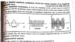
(| Principles of Electronics Communication (MSBTE) 2-4, , AM and FM Modulation, , , , , , _ If A, ie., amplitude of carrier is changed according to, modulating signal Amplitude modulation is obtained., , , , , , - If Fy, ie, frequency is changed according to, modulating signal, Frequency modulation is obtained., , - If @, ie. phase is changed according to modulating, signal, Phase modulation is obtained., , ~- While changing one parameter, we need to keep other, two, constant., , — Analog modulation can be of pulse modulation type as, shown in Fig. 2.4.1. In pulse modulation carrier signal, is in pulse format. Hence amplitude, width or duration, and position are the three parameters which can be, , , , , , , , , , , , , , , , , , , Sr. | Parameter Analog, No. ae A, 5. | Detection and | Not possible, correction of, errors, 6. | Bandwidth Lower, tequirement, 7. | Muttiplexing | FDM (frequency division | TDM (Time, scheme used | multiplexing) division, muttiplexing), 8. | Suitability for | Not suitable Suitable due to, military data encoding, applications methods, 9. | Types ‘AM, FM, PM, PAM, PPM, | PCM, DM, ADM,, PWM, etc, DPCM etc, , , , changed and PAM (pulse amplitude modulation),, PWM/PDM (pulse width modulation/pulse duration, modulation) and PPM (pulse position modulation) are, , , , , , obtained., (8) Digital modulation, - PCM (pulse code modulation), DM (delta modulation),, , , , 2.5 Amplitude Modulation, carrier is changed in accordance with, and phase constant is known as, ulation’. ¢, , , , , , , , , , , , ADM (adaptive delta modulation), DPCM (differential, pulse code modulation), etc. are some of the types of, digital modulation technique., , — For digital modulation, signal needs to be converted, from analog format to digital one with use of ADC, (analog to digital convertor)., , - Digital modulation gives output in binary word format., , - Comparison of analog and digital modulation, techniques is as shown in Table 2.4.1, Table 2.4.1 : Comparison of analog and digital, , , , , , , , - AM has advantage of being used with simple, modulators:and demodulators. But it has disadvantage, of poor noise immunity and wastage of transmitted, power., , — Applications include MF and HF broadcasting, aircraft, communication in VHF range, etc., , - With the little modifications, it can be used in other, variety of applications like television broadcasting and, long distance telephony, etc., , — Information is carried in the variations of amplitude, , changes in carrier wave. It is also called as linear, , , , , , , , , , , , , , , , , , , , , , , , , , , , , , , , , , , , modulation techniques modulation scheme., Pa Analog modulation Digital 2.5.1 Time Domain Representation of AM, No. modulation > (MSBTE - S-13, S-14, W-15, Dec.16), 1. F Natwe of | Analog Daina., transmitted ay Q.1 Draw the waveforms of AM wave with message, signal signal and carrier signal showing separately., 2. | Parameters | Amplitude, frequency or | Code words (Ref. Sec. 2.5.1) (S13, 1 Mark), that carry phase variations Q.2> Represent AM wave in the time domain., ina (Ref. Sec, 2.5.1) (8-14, 1 Mark)|, 3. | Noise Poor for AM but improves Excellent Q.3 Draw the AM signal representation in : (i) Time, immunity for FM and PM. Still poor domain. (Ref, Sec. 2.5.1) (W-15, 4 Marks), as compared to digital Q.4 Draw the time domain representation of AM wave..|, modulation techniques (Ref. Sec, 2.5.1) (W-16, 1 Mark), 4. | Use of Not used Used :, fepeaters TE, wad SACHIN SHAH Venture, , Tech-Neo Publications -....~.Where Authors inspire innovation

