Page 1 :
VARDHAMAN COLLEGE OF ENGINEERING, (AUTONOMOUS), Shamshabad – 501 218, Hyderabad, , DEPARTMENT OF ELECTRICAL AND ELECTRONICS ENGINEERING, Sem: IV sem, , Course Code: A3211, , Course Outcomes (COs):, After the completion of the course, the student will be able to, Apply the knowledge of basic principles and construction of AC machines for various industrial, C211.1, , and house hold applications., , C211.2, , Analyze the characteristics and performance of AC machines for a suitable application., , C211.3, , Evaluate the performance of any AC machine for different loading conditions., , C211.4, , Develop the equivalent circuit and phasor diagrams of any AC machine., , Lecture Notes, , 1, , Electrical Machines - II
Page 2 :
SYLLABUS, UNIT - I 3-Phase INDUCTION MOTORS: Polyphase induction motors-construction details of cage and, wound rotor machines-production of a rotating magnetic field - principle of operation - rotor emf, and rotor frequency - rotor reactance, rotor current and pf at standstill and during operation. Rotor, power input, rotor copper loss and mechanical power developed and their inter relation-torque, equation-deduction from torque equation - expressions for maximum torque and starting torque torque slip characteristic - double cage and deep bar rotors - equivalent circuit - phasor diagram crawling and cogging, UNIT - II CIRCLE DIAGRAM & SPEED CONTROL METHODS OF INDUCTION MOTORS: Circle diagramno load and blocked rotor tests-predetermination of performance-methods of starting and starting, current and torque calculations. Speed control-change of frequency; change of poles and methods of, consequent poles; cascade connection. Injection of an emf into rotor circuit (qualitative treatment, only)-induction generator-principle of operation., UNIT – III CONSTRUCTION AND PRINCIPLE OF OPERATION OF ALTERNATORS: Constructional, Features of round rotor and salient pole machines, Armature windings, Integral slot and fractional, slot windings; Distributed and concentrated windings, pitch and winding factors E.M.F Equation., Synchronous Generator Characteristics, Harmonics in generated E.M.F., suppression of harmonics,, armature reaction, leakage reactance, synchronous reactance and impedance, experimental, determination, phasor diagram, load characteristics., REGULATION OF SYNCHRONOUS GENERATOR: Regulation by synchronous impedance method,, M.M.F. method, Z.P.F. method and A.S.A. methods. Salient pole alternators, two reaction analysis,, experimental determination of Xd and Xq (Slip test) Phasor diagrams, Regulation of salient pole, alternators., UNIT – IV PARALLEL OPERATION OF SYNCHRONOUS GENERATOR: Synchronizing alternators with, infinite bus bars, synchronizing power torque, parallel operation and load sharing. Effect of change, of excitation and mechanical power input, Analysis of short circuit current wave form., Determination of sub-transient, transient and steady state reactance’s. SYNCHRONOUS, MOTORS:Theory of operation, phasor diagram, Variation of current and power factor with, excitation, synchronous condenser, Mathematical analysis for power developed., UNIT - V SINGLE PHASE MOTORS: Single phase Motors: Single phase induction motor,, Constructional features-Double revolving field theory – Elementary idea of cross-field theory, splitphase motors, shaded pole motor. SPECIAL MOTORS: Principle & performance of A.C. Series motor,, Universal motor. Principle of permanent magnet machines, stepper motors, TEXT BOOKS:, 1. J. B. Gupta (2006), Theory & Performance of Electrical Machines, 14th edition, S. K. Kataria& Sons,, New Delhi., 2. P. S. Bimbra(2000), Electrical Machinery, 7th edition, Khanna Publishers, New Delhi., REFERENCE BOOKS:, 1. A. E. Fritzgerald, C. Kingsley, S. Umans (2002), Electric Machinery, 5th edition, Tata McGraw Hill, Companies, New Delhi., 2. I. J. Nagrath, D. P .Kothari (2001), Electric Machines, 3rd edition, Tata McGraw Hill Publishers, New, Delhi., , Lecture Notes, , 2, , Electrical Machines - II
Page 3 :
UNIT-I, THREE PHASE INDUCTION MOTOR, An electric motor is a device, which converts electrical energy into mechanical energy. Motors can, operate on ac supply, single phase as well as three phase, called as ac motors., Ac motors are further classified as synchronous motors, single phase & three phase induction, motors and some special purpose motors., Out of all these types, three phase induction motors are commonly used for various applications in, industries. The principle of operation of three phase induction motors is based on the production of, rotating magnetic field., , Construction of Induction Motor:, , Conversion of electrical power into mechanical power takes place in the rotating part of an electric, motor. In dc motors, electrical power is conducted directly to the armature (rotating part) through, brushes and commutator. Hence a dc motor can be called as a conduction motor., However, in ac motors the rotor does not receive electric power by conduction but by induction in, exactly the same way as the secondary of a 2-winding transformer receives its power from the, primary. That is why such motors are known as Induction motors., An induction motor can be treated as a rotating transformer i.e., one in which primary winding is, stationary but the secondary is free to rotate., , Advantages, , Disadvantages, , 1., , It has very simple and, unbreakable construction, , 2., , Its cost is low and it is very reliable, , 3., , It has high efficiency, , 4., , It requires minimum maintenance, , 5., , It needs no extra starting motor for, starting, , Lecture Notes, , almost 1. Its speed cannot be varied without sacrificing, some of its efficiency, 2. Just like a dc shunt motor, its speed, decreases with increase in load, 3. Its starting torque is inferior to that of dc, shunt motor, , 3, , Electrical Machines - II
Page 4 :
Construction:, An induction motor consists essentially of two main parts., 1. Stator, 2. Rotor, Stator is the stationary part and rotor is the rotating part., , Stator:, Stator is made up of a number of stampings which are slotted to receive the windings. The stator, carries a 3- phase winding and is fed from a 3-phase supply. It is wound for a definite number of, poles, the exact number of poles being determined by the requirements of speed. Greater the, number of poles, lesser the speed and vice versa. The stator windings when supplied with 3-, currents produce a magnetic flux which is of constant magnitude but which revolves at synchronousspeed given by Ns=120f/p. This revolving magnetic flux induces an emf in the rotor by mutual, induction., Rotor:, a. Squirrel-Cage rotor: Motors employing this type of rotor are known as squirrel cage, induction motors., b. Phase-wound or wound rotor: Motors employing this type of rotor are known as phasewound motors or wound motors or slip-ring motors., , Lecture Notes, , 4, , Electrical Machines - II
Page 5 :
Squirrel-Cage Rotor:, , 90% of induction motors are squirrel-cage type, because this type of rotor has the simplest and most, rugged construction. The rotor consists of a cylindrical laminated core with parallel slots for carrying, the rotor conductors and these slots are not wires but consists of heavy bars of copper, aluminium, or alloys. The rotor bars are permanently short-circuited on themselves. Hence, it is not possible to, add any external resistance in series with rotor circuit for staring purposes. One bar is placed in each, slot. The rotor bars are brazed or electrically welded or bolted to two heavy and stout short, circuiting end rings thus giving a squirrel-cage construction., The rotor slots are usually not quite parallel to the shaft but are purposely given a slight skew. This is, useful as:, a) it helps to make the motor run quietly by reducing the magnetic hum, b) it helps in reducing the locking tendency of the rotor i.e., the tendency of the rotor teeth to, remain under the stator teeth due to direct magnetic attraction between the two., , Phase-wound Rotor:, , Lecture Notes, , 5, , Electrical Machines - II
Page 6 :
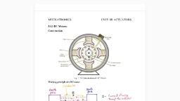
This type of rotor is provided with 3-, double-layer, distributed winding consisting of coils. The, rotor is wound for as many poles as the number of stator poles and is always wound 3-phase even, when the stator is wound two-phase. The three-phases are starred internally and the construction is, complicated., The slip rings are mounted on the shaft. One end of each phase winding, after connecting the, winding in star or delta is connected to the slip ring. Thus there are three slip rings mounted on the, shaft with brushes resting on them. These three brushes are further externally connected to three, phase star connected rheostat. This makes possible the introduction of additional resistance in the, rotor circuit during the starting period for increasing the starting torque of the motor. When running, under normal conditions, the slip-rings are automatically short-circuited by means of a metal collar, which is pushed along the shaft and connects all the rings together. Next, the brushes are, automatically lifted from the slip rings to reduce the frictional losses & the wear & tear & hence, under normal running conditions, the wound rotor is short-circuited on itself just like the squirrel, cage rotor., , The main parts of a slip-ring motor are:, 1. Frame-made of cast-iron, 2. Stator and Rotor core made of high quality low loss silicon steel laminations and with, enhanced insulation., 3. Stator and rotor windings- More moisture proof insulation embodying mica and high quality, varnish., 4. Shafts and bearings: Ball and roller bearings are used to suit heavy duty trouble free running., 5. Fans: Light aluminium fans are used for adequate circulation of cooling air., 6. Slip-rings and Slip ring enclosures: Slip-rings are made of high quality phosphor-bronze and, are of moulded construction., Principle of operation:, When the 3- stator windings are fed by 3- supply then a rotating magnetic field of constant, magnitude is produced. This field rotates at synchronous speed N s. This rotating flux cuts the rotor, conductors which are stationary and due to relative speed between the rotating flux and the, stationary conductors, an emf is induced in the latter according to Faraday’s law of Electro-magnetic, induction., The frequency of the induced emf is the same as the supply frequency. Its magnitude is proportional, to the relative velocity between the flux and the conductors and its direction is given by Fleming’s, right hand rule., Since the rotor bars or conductors form a closed circuit, rotor current is produced in the rotor bars in, case of squirrel cage or in the rotor phases in the case of slip ring whose direction as given by Lenz’s, law is such as to oppose the very cause producing it., The rotor currents and the stator magnetic field interact with each other to produce a torque and, hence the rotor rotates., Lecture Notes, , 6, , Electrical Machines - II
Page 7 :
Hence, the very cause of producing the current is the relative speed between the rotating field and, the stationary rotor and to reduce this relative speed, the motor starts running in the same direction, as that of the flux and tries to catch up., Rotating Magnetic Field (RMF):, It is defined as the field or flux having constant amplitude but whose axis rotates in a plane at a, certain speed eg. permanent magnet rotating in a space produces a rotating magnetic field. If an, arrangement is made to rotate the poles, with constant excitation supplied, the resulting field is, rotating magnetic field. Such a rotating magnetic field can also be produced by exciting a set of, stationary coils or windings with the help of ac supply. The resultant flux produced in such a case has, constant magnitude and its axis rotates in space without physically rotating the windings. The, rotating flux or rotating magnetic field also bears a fixed relationship between number of poles,, frequency of ac supply and speed of rotation., Ns , , 120 f, P, , Hence rotating magnetic field always rotates with a speed equal to synchronous speed. When three, phase supply is given to the stationary three phase winding, the resultant flux produced is rotating in, space having constant amplitude and with synchronous speed Ns which depends on frequency of, three phase supply and the number of poles for which the three phase stationary winding is wound., This flux is rotating magnetic field., , Production of Rotating Field:, When the stationary coils, wound for two or three phases, are supplied by two or three-phase, supply respectively, a uniformly-rotating (revolving) magnetic flux of constant value is produced., , Two-phase supply:, The principle of a 2-, 2-pole stator having two identical windings 90 space degrees apart is shown:, The flux due to the current flowing in each phase winding is assumed sinusoidal and is shown below., The assigned positive directions of fluxes are shown below., , Lecture Notes, , 7, , Electrical Machines - II
Page 9 :
Let 1 and 2 be the instantaneous values of the fluxes set up by the two windings. The resistant flux, r at any time is the vector sum of these two fluxes (1 and 2) at that time. We will consider, conditions at intervals of 1/8th of a time period i.e., at intervals corresponding to angle of 00, 450, 900,, 1350, 1800. The resultant flux r is constant in magnitude i.e., equal to m, the maximum flux due to, either phase and is making one revolution/cycle. That is, the resultant flux rotates synchronously., a) When = 00 i.e., corresponding to point ‘0’ in the figure, 1 = 0, but 2 is maximum i.e., equal to, m and is negative. Hence, resultant flux r = m and being negative is shown by a vector pointing, down words., b) When = 450, i.e., corresponding to point 1. At this instant 1= m/ 2 and is positive., 2= m/ 2 but is still negative. Their resultant r=, , , , n, , / 2, , , 2, , m, , / 2, , , , 2, , = m, , c) When = 900, i.e., corresponding to point 2 in figure. Here 2=0 but 1=m and is positive. Hence, r=m and has further shifted by an angle of 450 from its position in (b) or by 900 from its original, position in (a)., , d) When = 1350, i.e., corresponding to point 3 in figure. Here 1=m/ 2 and is positive,, 2= m/ 2 and is also positive. The resultant r= m and has further shifted clockwise by another 450, as shown., , e) When = 1800 i.e., corresponding to point 4 in figure. Here 1=0, 2= m and is positive. Hence r =, m and has shifted clockwise by another 450 or has rotated through an angle of 1800 from its position, at the beginning as shown., , =0o, , =90o, r=1=m, , =45o, , r=m, r= 2= m, , =180o, =135o, Lecture Notes, , 9, , Electrical Machines - II
Page 10 :
r=m, , r=m=2, , Hence, we can conclude that:, 1) the magnitude of the resultant flux is constant and is equal to m, the maximum flux due to, either phase., 2) that the resultant flux rotates at synchronous speed given by Ns = 120 f/P rpm, Three-phase Supply:, When three-phase windings are displaced in time by 120 0, then they produce a resultant magnetic, flux, which rotates in space as if actual magnetic poles were being rotated mechanically. The, principle of a 3- two-pole stator having three identical windings placed 120 0 space degrees apart is, shown., , 1200, 1200, , 1200, Lecture Notes, , 10, , Electrical Machines - II
Page 11 :
Let the maximum value of flux due to any one of the three phases be m. The resultant flux r at any, instant is given by the vector sum of the individual fluxes, 1, 2 & 3 due to three phases., We will consider values of r at four instants, 1/6th time-period apart & corresponding to points, marked 0, 1, 2 & 3., 1) When = 00 i.e., corresponding to point 0 in figure. 1 =0, 2 = -, , 3, 3, m , 3 =, m ,, 2, 2, , Vector of 2 is drawn in a direction opposite to the direction around positive., r 2, , 3, 60, 3, 3, m cos, 3, m m, 2, 2, 2, 2, , 2) When = 600 i.e., corresponding to point 1. Here 1 =, , 3, m drawn parallel to O I, 2, , 3, m drawn in opposition to O I, 2, , 2 =3 = 0, , r= 2 X, , 3, 3, m, m X cos 30 =, 2, 2, 3, 2, , The resultant flux is m but has rotated clock wise through an angle of 600., c) When = 1200, i.e., corresponding to point 2, 1 =, , 3, 3, m , 2 =0, 3= m, 2, 2, , 3, m, 2, 3, The resultant is m again but has further rotated clockwise through an angle of 600., 2, , r =, , d) When = 1800, i.e., corresponding to point 3, in figure, 1 =0, 2 =, , The resultant is, , 3, 3, m , 3 = m, 2, 2, , 3, m and has rotated clockwise by an additional angle of 60 0 or through an angle of, 2, , 1800 from the start., , Lecture Notes, , 11, , Electrical Machines - II
Page 12 :
3, -2, , 60, , 1, , 0, , -2, r=1.5m, , r=1.5m, , 1)=00 2)=600, , r=1.5m r=1.5m, , -3, -3, 1, 3)=1200, , 2, , 4)=1800, , Hence, we conclude that:, 1. The resultant flux is of constant value = 3/2 m i.e., 1.5 times the maximum value of the flux due, to any phase., 2. The resultant flux rotates around the stator at synchronous speed given by, Ns = 120 f / p, , Slip:, The rotor never succeeds in catching up with the stator field because if it really did so, then there, would be no relative speed, no emf, no rotor current and hence no torque. The rotor falls back, behind the magnetic field by a certain speed which is necessary for the operation of an induction, motor and the difference in speed depends upon the load on the motor., The difference between the synchronous speed Ns and the actual speed N of the rotor is known as, slip speed., % slip s =, , NS N, NS, , Ns - N = slip speed, N = Ns (1 - s), , Lecture Notes, , 12, , Electrical Machines - II
Page 13 :
The revolving flux is rotating synchronously relative to the stator (i.e., stationary space) but at slip, speed relative to the rotor., , Frequency of rotor current:, When the rotor is stationary the frequency of rotor current is the same as the supply frequency. But, when the rotor starts revolving, then the frequency depends upon the relative speed or on slipspeed., Let at any slip–speed, the frequency of the rotor current be f. Then, Ns - N = 120 f/P, Ns = 120 f/P, f/f = Ns - N/Ns = s, f= sf, Motor current has a frequency of f= sf and when flowing through the individual phases of rotating, winding give rise to rotor magnetic fields., These individual rotor magnetic fields produce a combined rotating field whose speed relative to, rotor is, 120f/P = 120Sf/P = SNs, However, the rotor itself is rotating at speed N with respect to space. Hence speed of rotor field in, space = speed of field relative to rotor + speed of rotor relative to space:, = SNs + N = SNs + Ns (1-S) = Ns, what ever may be the value of slip, rotor current and stator currents each produce a sinusoidally, distributed magnetic field of Ns., That is, both the rotor and stator fields rotate synchronously which means that they are stationary, w.r.t. each other., , PROBLEMS:, 1. A 3 –phase I. M. is wound for 4 poles and is supplied from 50 Hz system. Calculate (1), Synchronous-speed (2) rotor speed, when slip is 4% (3) rotor frequency when rotor runs at, 600 rpm., Ns = 120f/P, , = 120 x 50/4 = 1500 rpm, , Ns = Ns (1-s) = 1500 (1-0.04) = 1440 rpm, When rotor speed is 600 rpm, slip is, s = (Ns – N)/Ns = (1500-600)/1500 = 0.6, , Lecture Notes, , 13, , Electrical Machines - II
Page 14 :
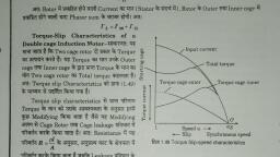
Rotor current frequency f’ = sf = 0.6 x 50 = 30Hz, , 2. A 3- 6-pole 50Hz induction motor has a slip of 1% at no load and of 3% at full, load. Find (A) synchronous speed (B) no – load speed (C) full-load speed., (D) frequency of rotor–current at stand still and (E) frequency of rotor-current at, full-load, P = 6, f = 50Hz S = 0.01 at no load, S = 0.03 at full load, A), B), C), D), , Synchronous speed Ns = 120f/P = 120 x 50/60 = 1000 rpm, No-load speed N = Ns (1-s) = 1000 (1-0.01) = 990 rpm, Full load speed = N = Ns (1-s) = 1000 (1-0.03) = 970 rpm, At standstill, S= 1 therefore, the rotor-current frequency fr = f.S. = 50x, 1=50 Hz, E), At full-load S = 0.03, fr = f S = 50 x 0.03 = 1.5 Hz, 3. A 12-pole 50 Hz 3. I. M. runs at 485 rpm what is the frequency of rotor – current., P = 12, f = 50, N = 485 rpm, Ns = 120f/P = 120x50/P = 500 rpm, S = Ns-N = 500-485/500 = 0.03 = 3%, fr = S.f. = 50 x 0.03 = 1.5 Hz, , Relation between Torque and Rotor Power factor:, In case of dc motor, the torque Ta is proportional to the product of armature current and flux per, pole i.e. Ta Ia., In case of an Induction motors the torque is also proportional to the product of flux per stator pole, and the rotor current. There is one more factor that has to be taken into account i.e., the power, factor of rotor., T I 2 cos 2, or T = K I2 cos 2, Where I2 = rotor current at stand still, 2 = angle between rotor emf and rotor current, k = constant, let the rotor emf at stand still be E2., E2 , T E2 I2 cos2, T = k1 E2 I2 cos2, The effect of rotor power factor on motor torque for various values of 2 is shown from the above, equation of torque, it is clear that as 2 increases then cos2 decreases & hence torque decreases, and vice versa., , Lecture Notes, , 14, , Electrical Machines - II
Page 15 :
Starting Torque:, Torque = Turning or twisting moment force about an axis., The torque developed by the motor at the instant of starting is called starting torque., In some cases, it is greater than the normal running torque whereas in some other cases it is, somewhat less., Let E2 = rotor emf per phase at standstill, R2 = rotor resistance / phase, X2 = rotor reactance/ phase at standstill., Z2 = R22 + X22 = rotor impedance / phase at standstill., I2 = E2/Z2 = E2/R22+X22;, cos 2 = (R2/Z2) = R2/(R22 + X22), Starting torque Tst = K1 E2 I2 cos 2., If supply voltage V is constant, then the flux and hence E2 both are constant, Tst = K2 R2/R22 + x22 = K2/R2 Z2 where k2 is some other constant., , Starting torque of a squirrel cage motor:, The resistance of a squirrel-cage rotor is fixed & small as compared to its reactance which is very, large especially at the start because at stand till, the frequency of the motor currents equals the, supply frequency. Hence the starting current I2 of the rotor though very large in magnitude lags by a, very large angle behind E2, with the result that the starting torque per ampere is very poor. It is, roughly 1.5 times the full load torque although the starting current is 5 to 7 times the full-load, current. Hence, such motors are not useful where the motor has to start against heavy loads., , Starting torque of a slip-ring motor:, The starting torque of such a motor is increased by increasing its power factor by adding external, resistance in the rotor circuit from the star connected rheostat, the rheostat resistance being, progressively cut out as the motor gains speed., Addition of external resistance, however, increases the rotor impedance and so reduces the rotor, current. At first, the effect of improved power factor predominates the current-decreasing effect of, impedance. Hence, starting torque is increased., But after a certain point, the effect of increased impedance predominates the effect of improved, power factor and so the torque starts decreases., , Torque – Slip Characteristics:, As an induction motor is loaded from no load to full load, its speed decreases hence slip increases., Due to increased load, motor has to produce motor torque to satisfy load demand. The torque, ultimately depends on slip as explained earlier. The behavior of motor can be easily judged by, sketching a curve obtained by plotting torque produced against slip of induction motor. The curve, obtained by plotting torque against slip from S = 1 at start) to S = 0 (at synchronous speed) is called, Lecture Notes, , 15, , Electrical Machines - II
Page 16 :
torque – slip characteristics of the induction motor. It is very interesting to study the nature of, torque – slip characteristics., We have seen that for a constant supply voltage E2 is also constant. So we can write torque, equations as, T , , sR2, , R22, , sX 2 , , 2, , Now to judge the nature of torque – slip characteristics let us divide the slip range (S = 0 to S = 1), into two parts and analyse them independently., , Stator Current, Maximum Torque, Torque, , Torque, , T∞1/S, , T∞S, , S=0, , Slip, , S=1, Speed, , i) Low slip region: In low slip region, ‘S’ is very very small. Due to this, the term (SX 2)2 is so small as, compared to R22 that it can be neglected., T, , SR2, R22, , S, , as R2 is constant, , Hence in low slip region, torque is directly proportional to slip. So as load increases, speed, decreases, increasing the slip. This increases the torque which satisfies the load demand. Hence, the, graph is straight line in nature., At N = Ns, s = 0 hence T = 0. As no torque is generated at N = Ns, motor stops if it tries to achieve the, synchronous speed. Torque increases linearly in this region of low slip values., ii) High slip region: In this region, slip is high i.e. slip value is approaching to 1. Here it can be, assumed that the term R22 is very very small as compared (s X2)2. Hence neglecting the term R22 from, the denominator, we get,, T, , SR2, , S, , X2 , , 2, , , , 1, where R2 and X2 are constants., S, , So in this region, torque is inversely proportional to the slip. Hence its nature is like rectangular, hyperbola., Lecture Notes, , 16, , Electrical Machines - II
Page 17 :
Now when load increases, load demand increases but speed decreases. As speed decreases, slip, increases. In high slip region as T 1/S, torque decreases as slip increases. But torque must increase, to satisfy the load demand. As torque decreases due to extra loading effect speed further decreases, and slip further increases. Again torque decreases as T 1/S hence same load act as an extra load, due to reduction in torque produced. Hence speed further drops. Eventually motor comes to, standstill condition. The motor cannot continue to rotate at any point in this high slip region. Hence, this region is called unstable region of operations., So torque – slip characteristics has two parts,, i), ii), , straight line called stable region of operation, Rectangular hyperbola called unstable region of operation., , Losses in an Induction Motor:, The various power losses in an induction motor can be classified as, a) Constant losses, b) Variable losses, Constant Losses:, These can be further classified as Core losses or mechanical losses. Core losses occur in stator core, and rotor core. These are also called as iron losses. These losses include eddy current losses and, hysteresis losses., The eddy current losses are minimized by using laminated construction while hysteresis losses are, minimized by selecting high grade silicon steel as the material for stator and rotor., Mechanical, Losses include frictional losses at the bearings and windage losses., Variable Losses:, This includes the copper losses in stator and rotor winding due to current flowing in the winding. As, current changes when load changes these losses are said to be variable losses., Power distribution diagram of an I.M:, , M otor input in stator P 1, , Stator Cu & iron, los s es (P C u & P i ), , rotor input or stator output (P 2 ), , rotor Cu los s (P C U ), , M ec hinc al p o w er d e velo p e d, P m, or gr os s rotor output, P g, , win d a g e & friction los s, , Lecture Notes, , 17, , rotor output or m otor, output (P o ut ), , Electrical Machines - II
Page 18 :
Torque developed by an I.M:, An induction motor develops gross torque Tg due to gross rotor output Pm., Its value can be expressed either in terms of rotor input P2 or rotor output Pm, Tg= P2/ws =, , =, , p2, in terms of rotor input, 2N, , pm, p, = m in terms of rotor output, 2N, w, , The starting torque Tsh is due to output power Pout which is less than Pm because of rotor friction and, windage losses., Ts h , , pout, pout, , w, 2N, , The difference between Tg and Tsh equals the torque lost due to friction and windage loss in the, motor., P2, P, 60 P2, , X, 9.55 2 N m, 2Ns / 60 2, Ns, Ns, Pm, Pm, 60 Pm, , X, 9.55, Nm, =, 2N / 60 2, N, N, Pout, P, 60 Pout, , X, 9.55 out N m, Tsh=, 2N / 60 2, N, N, , Tg=, , Torque, mechanical power and Rotor output:, Stator input P1 = stator output + stator losses, Rotor input P2= stator output, Rotor gross output, Pm= rotor input P2 – rotor losses, This rotor output is converted into mechanical energy and gives rise to gross torque Tg, Out of this gross torque developed, some is lost due to windage and friction losses in the rotor and, the rest appears as the useful or shaft torque Tsh. Let N rps be the actual speed of the rotor and if Tg, is in N-m, then, Tg x 2N = rotor gross output in watts Pm, Tg=, , rotor gross output in watts, 2N, , , , (1), , If these were no Cu losses in the rotor, then rotor output will equal rotor input and the rotor will run, at synchronous speed,, , Tg=, , rotor input P2, 2Ns, , , , (2), , From (1) and (2), we get, Lecture Notes, , 18, , Electrical Machines - II
Page 19 :
Rotor gross output Pm= Tg 2N, Rotor input = P2= Tgws= Tg x 2Ns, , , , (3), , The difference of the two equals rotor Cu loss., rotor Cu loss = P2 - Pm = T x 2(Ns – N), Form (3) and (4), , (4), , rotor Cu loss N s N, , S, rotor input, Ns, , rotor Cu loss = S X rotor input, = S X power across air gap = SP2, Rotor input =, , rotorCu loss, S, , Rotor gross output Pm= input P2- rotor Cu loss, = input – S X rotor input, = (1-S) input P2, rotor gross output Pm= (1-S) rotor input P2, rotor gross output Pm, N, 1 S , rotor input P2, Ns, , Pm, N, , P2, Ns, , rotor efficiency =, , N, Ns, , And, rotor Cu loss, S, , rotor gross output 1 S, , If some power P2 is delivered to rotor, then a part SP2 is lost in the rotor itself as copper loss and the, remaining (1-S) P2 appears as gross mechanical power Pm, P2: Pm : I2R :: 1: (1-S) : S, or P2: Pm : Pc :: 1: (1-S) : S, The rotor input power will always divide itself in this ratio, hence it is advantageous to run the motor, with as small ship as possible., , Lecture Notes, , 19, , Electrical Machines - II
Page 20 :
Problems:, 1. The motor emf of a 3-, 6-pole, 400V, 50 Hz I.M alternates at 3Hz. Compute the speed and, percentage slip of the motor. Find the rotor Cu loss per phase if the full input to the motor is, 119.9 kw., S=, , fr, 3, , 0.06 or 6%, f, 50, , Ns= 120 X, , 50, 1000 rpm, 6, , N= (1-S) Ns = (1-0.06) 1000= 940 rpm, Rotor input = 111.9 kw, Rotor Cu loss= s X rotor input, = 0.06 X 111,900, = 6715 w, loss/phase=, , Lecture Notes, , 6715, 2238w, 3, , 20, , Electrical Machines - II